Maverick/Slider: Difference between revisions
No edit summary |
|||
| Line 35: | Line 35: | ||
= Defining a Region of Interest for the Fixed Image = | = Defining a Region of Interest for the Fixed Image = | ||
[[Image:Screenshot-Slider-3-FixedROI.png|center| | [[Image:Screenshot-Slider-3-FixedROI.png|center|400px]] | ||
The fixed and moving images loaded, you can now define a region of interest for the fixed image. ROIs are used to limit the need of memory in the next steps. This is particularly useful when the images sizes and resolutions are different; the result image can get very big ( low-def heaf registered with a high-def eye, the result high-def head may use > 6GB of RAM ). By moving the anchor points of the 3D box widget in the 3D view, the final ROI of the fixed image is set. Click on <b>Next></b> to apply your changes.<br> | The fixed and moving images loaded, you can now define a region of interest for the fixed image. ROIs are used to limit the need of memory in the next steps. This is particularly useful when the images sizes and resolutions are different; the result image can get very big ( low-def heaf registered with a high-def eye, the result high-def head may use > 6GB of RAM ). By moving the anchor points of the 3D box widget in the 3D view, the final ROI of the fixed image is set. Click on <b>Next></b> to apply your changes.<br> | ||
In our example we want to keep the whole volume of Billie, this is why set the size of the ROI to be the same than the volume ( default ). | In our example we want to keep the whole volume of Billie, this is why set the size of the ROI to be the same than the volume ( default ). | ||
= Defining a Region of Interest for the Moving Image = | = Defining a Region of Interest for the Moving Image = | ||
[[Image:Screenshot-Slider-4b-MovingROI.png|center| | [[Image:Screenshot-Slider-4b-MovingROI.png|center|400px]] | ||
Modify the moving image region of interest and click <b>Next</b> to apply.<br> | Modify the moving image region of interest and click <b>Next</b> to apply.<br> | ||
In our example, we shrink the ROI to the size of the head only as we want only the head of Duke in the final image. | In our example, we shrink the ROI to the size of the head only as we want only the head of Duke in the final image. | ||
= Initial Registration = | |||
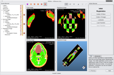
[[Image:Screenshot-Slider-5-InitialRegistration.png|center|400px]] | |||
A new layout is applied. At any time you can display a different layout by clicking one of the top left icons [[Image:Screenshot-Slider-LayoutBar.png]] respectively: 3D, 2D, 3D+3x2D, 9x2D, 2x(3D+2D) and 2x2D+Checkerboard+3D ).<br> | |||
On the left, a <b>Scene Browser</b> widget displays the hierarchy of all the objects of the scene. Visibility of the objects can be toggled by clicking on the eye icon [[Image:Screenshot-Slider-Visibility.png]]. A right click on the eye shows a slider bar that controls the objects opacity.<br> | |||
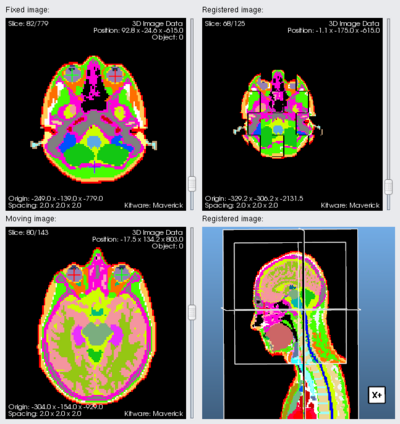
The top left 2D view and bottom left 2D view display the fixed image and the moving image respectively. The top right 2D view is a <b>checkerboard</b> view. It simultaneously displays the fixed and the moving image. The view would have only few discontinuities if the 2 images are well aligned. The bottom right 3D view is a view of the scene that contains the 3 orthogonal planes of the fixed and moving images.<br> | |||
<br> | |||
In order to help the registration algorithm, a basic alignment between the fixed and the moving images is needed. The 2 loaded images can have different orientation, spacing, size... The result of the misalignment between the volumes can be noticed in the top right 2D checkerboard view and in the bottom right 3D view. There are 4 different ways to align the fixed and the moving images together. The user can click on one of the following buttons: | |||
*<b>Center of Mass</b> | |||
The centers of mass of the images are computed. The moving image is then translated by a vector defined by the centers. | |||
*<b>Center of Images</b> | |||
The centers of the images are computed. The moving image is then translated by a vector defined by the centers. | |||
*<b>Landmarks</b> | |||
[[Image:Screenshot-Slider-6-LandmarksMenu.png]] | |||
At least 3 landmarks must be dropped in the fixed and the moving image to define a transform matrix. The transform matrix is applied to the moving image. To refine the transformation, more landmarks can be used.<br> | |||
For each landmark placed in the fixed image must correspond the same landmark in the moving image. For example, if you place the first landmark in the center of the left eye in the fixed image, the landmark in the moving image shall be in the center of the left eye as well (beware of the orientation of the 2D slices that can be different).<br> | |||
Landmarks can be edited with a click and by using the drag&drop mechanism. When the <b>Add Landmark</b> button is clicked, 2 landmarks with the same colors are created. The first landmark is placed in the fixed image, the other in the moving image. The default location of the landmarks is the last position in the views the user clicked.<br> | |||
A good practice is to blindly click where the next landmarks must placed in the fixed and the moving image. Click then on <b>Add Landmark</b>.<br> | |||
If a landmark is selected ( bold and underline in the Scene Browser list ), any click in the 2D view moves the landmark. If you change the current view using the slider, the selected landmark moves. You can <b>lock</b> the landmark by clicking the locker [[Image:Screenshot-Slider-Mutable.png]] in the Scene Browser widget.<br> | |||
{| | |||
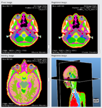
|[[Image:Screenshot-Slider-6a-AddLandmarks.png|thumb|200px|1st landmark in the right eye]] | |||
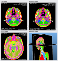
|[[Image:Screenshot-Slider-6b-AddLandmarks.png|thumb|200px|2nd landmark in the left eye]] | |||
|[[Image:Screenshot-Slider-6c-AddLandmarks.png|thumb|200px|3rd landmark in the corpus callosum ]] | |||
|[[Image:Screenshot-Slider-6d-AddLandmarks.png|thumb|200px|4th landmark at the bottom of the chin]] | |||
|- | |||
|[[Image:Screenshot-Slider-6e-AddLandmarks.png|thumb|200px|5th landmark in the 5th vertebrae]] | |||
|[[Image:Screenshot-Slider-6f-AddLandmarks.png|thumb|200px|6th landmark where the skull ends in the back of the head]] | |||
|[[Image:Screenshot-Slider-6g-AddLandmarks.png|thumb|200px|7th landmark in the back of the neck]] | |||
|[[Image:Screenshot-Slider-6h-AddLandmarks.png|thumb|200px|8th landmark in the trachea ]] | |||
|} | |||
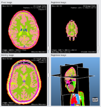
[[Image:Screenshot-Slider-6i-AddLandmarks.png|center|400px]] | |||
After the 3rd landmark is placed, Dukes head is moved (by the computed transform matrix) to the same position of Billie's head. However, the scale and the orientation is still not correct. More landmarks are added to refine the alignment. The difficulty in this example is that Duke is looking forward while Billie is looking down. By using the landmarks we can <i>bend</i> Duke's head. | |||
*<b>Load a Transform</b> | |||
You can import any transform saved in a ITK transform file format. You can reload any previously saved transform. After placing landmarks on low-res images, you can <b>Save Transform</b> for a later useon higher resolution images. | |||
Revision as of 19:59, 27 April 2009
Slider
Slider is the Registration Application of Maverick. The application registers an image (moving) into an other image (fixed). Below is a short tutorial to use Slider.
Before starting
Slider can import images ( *.mha *.mhd *.gipl *.jpg *.bmp *.nrrd ) and scenes (*.mrml). By loading a scene in Slider, you can extract any image from the scene. Importing a scene can be useful if you want to import a LabelMap. Loading a LabelMap directly (*.mha) will not contain any label description, this is why you should load the LabelMap through a scene. You can use Maverick/Merlin to create MRML scenes ( e.g. use the Resample module to lower the resolution of your images ).
In this tutorial, we register two bodies from the Virtual Family. Duke(moving image) is registered with Billie(fixed image). A result image is saved with the head of Duke and the body of Billie. Billie and Duke are stored in separate mrml scene files. We previously made sure that they shared the same tissue file.
Here is the list of the files used for this tutorial:
- Duke.mrml
- kwDuke_34y_V5_2mm.mha
- VirtualTissue.csv
- Billie.mrml
- kwBillie_11y_V2_2mm.mha
- VirtualTissue.csv
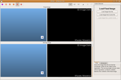
Loading a Fixed Image
The first screen invites you to select a fixed image. An image can be directly from a file or from a scene file. Loading a scene leads to another screen menu that lists all the volumes contained by the scene file. A volume must be selected from the list before clicking on Load Image. If the fixed and moving images are both contained by the loaded scene, Load Image and Scene loads the fixed image and cache the other volumes contained by the scene so they can be later used in the Load Moving Image menu.
In our example, we first click on Load Image from Scene File, in the new menu we choose kwBillie_11y_V2_2mm in the volume list to finally click Load Image.
The fixed image (the labelmap of Billie) is loaded in the top 3D and 2D views.
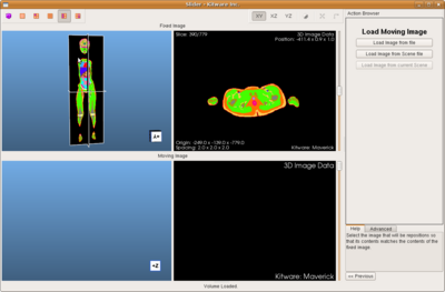
Loading a Moving Image
The second screen Load Moving Image invites you to select a moving image. This is the image to be registered with the already loaded fixed image. The process is the same than for the fixed image loading menu. If a scene has been previously loaded using Load Image and Scene, a third choice Load Image from Current Scene is available and allow the user to select a volume from the cache.
In our example, we click on Load Image from Scene File, in the next menu we choose kwDuke_34y_V5_2mm.mha in the volume list to finally click Load Image.
The moving image (the labelmap of Duke) is loaded in the bottom 3D and 2D views.
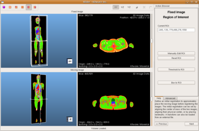
Defining a Region of Interest for the Fixed Image
The fixed and moving images loaded, you can now define a region of interest for the fixed image. ROIs are used to limit the need of memory in the next steps. This is particularly useful when the images sizes and resolutions are different; the result image can get very big ( low-def heaf registered with a high-def eye, the result high-def head may use > 6GB of RAM ). By moving the anchor points of the 3D box widget in the 3D view, the final ROI of the fixed image is set. Click on Next> to apply your changes.
In our example we want to keep the whole volume of Billie, this is why set the size of the ROI to be the same than the volume ( default ).
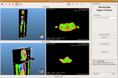
Defining a Region of Interest for the Moving Image
Modify the moving image region of interest and click Next to apply.
In our example, we shrink the ROI to the size of the head only as we want only the head of Duke in the final image.
Initial Registration
A new layout is applied. At any time you can display a different layout by clicking one of the top left icons
respectively: 3D, 2D, 3D+3x2D, 9x2D, 2x(3D+2D) and 2x2D+Checkerboard+3D ).
On the left, a Scene Browser widget displays the hierarchy of all the objects of the scene. Visibility of the objects can be toggled by clicking on the eye icon
. A right click on the eye shows a slider bar that controls the objects opacity.
The top left 2D view and bottom left 2D view display the fixed image and the moving image respectively. The top right 2D view is a checkerboard view. It simultaneously displays the fixed and the moving image. The view would have only few discontinuities if the 2 images are well aligned. The bottom right 3D view is a view of the scene that contains the 3 orthogonal planes of the fixed and moving images.
In order to help the registration algorithm, a basic alignment between the fixed and the moving images is needed. The 2 loaded images can have different orientation, spacing, size... The result of the misalignment between the volumes can be noticed in the top right 2D checkerboard view and in the bottom right 3D view. There are 4 different ways to align the fixed and the moving images together. The user can click on one of the following buttons:
- Center of Mass
The centers of mass of the images are computed. The moving image is then translated by a vector defined by the centers.
- Center of Images
The centers of the images are computed. The moving image is then translated by a vector defined by the centers.
- Landmarks
At least 3 landmarks must be dropped in the fixed and the moving image to define a transform matrix. The transform matrix is applied to the moving image. To refine the transformation, more landmarks can be used.
For each landmark placed in the fixed image must correspond the same landmark in the moving image. For example, if you place the first landmark in the center of the left eye in the fixed image, the landmark in the moving image shall be in the center of the left eye as well (beware of the orientation of the 2D slices that can be different).
Landmarks can be edited with a click and by using the drag&drop mechanism. When the Add Landmark button is clicked, 2 landmarks with the same colors are created. The first landmark is placed in the fixed image, the other in the moving image. The default location of the landmarks is the last position in the views the user clicked.
A good practice is to blindly click where the next landmarks must placed in the fixed and the moving image. Click then on Add Landmark.
If a landmark is selected ( bold and underline in the Scene Browser list ), any click in the 2D view moves the landmark. If you change the current view using the slider, the selected landmark moves. You can lock the landmark by clicking the locker
in the Scene Browser widget.
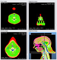
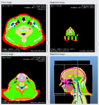
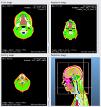
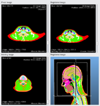
After the 3rd landmark is placed, Dukes head is moved (by the computed transform matrix) to the same position of Billie's head. However, the scale and the orientation is still not correct. More landmarks are added to refine the alignment. The difficulty in this example is that Duke is looking forward while Billie is looking down. By using the landmarks we can bend Duke's head.
- Load a Transform
You can import any transform saved in a ITK transform file format. You can reload any previously saved transform. After placing landmarks on low-res images, you can Save Transform for a later useon higher resolution images.
