Beginning Filters Python: Difference between revisions
(New page: =Introduction= ParaView filters This usecase shows a user how to use filters to modify the display of data. All filter examples assume that the user starts with a new model. To start o...) |
No edit summary |
||
| (10 intermediate revisions by the same user not shown) | |||
| Line 16: | Line 16: | ||
>>> Show(reader) | >>> Show(reader) | ||
>>> Render() | >>> Render() | ||
</source> | |||
[[Image:ClipFilterPython1.png|800px]] | |||
<source lang="python"> | |||
>>> clipFilter = Clip(reader) | >>> clipFilter = Clip(reader) | ||
>>> Hide(reader) | >>> Hide(reader) | ||
>>> Show(clipFilter) | >>> Show(clipFilter) | ||
>>> Render() | >>> Render() | ||
</source> | |||
[[Image:ClipFilterPython2.png|800px]] | |||
<source lang="python"> | |||
#get camera | #get camera | ||
>>> camera = GetActiveCamera() | >>> camera = GetActiveCamera() | ||
| Line 30: | Line 36: | ||
>>> camera.SetPosition(4.15603, 30, -35) | >>> camera.SetPosition(4.15603, 30, -35) | ||
>>> Render() | >>> Render() | ||
</source> | |||
[[Image:ClipFilterPython3.png|800px]] | |||
<source lang="python"> | |||
#we can see what's going on a little better | #we can see what's going on a little better | ||
>>> clipFilter.UseValueAsOffset = 1 | >>> clipFilter.UseValueAsOffset = 1 | ||
>>> clipFilter.Value = 5 | >>> clipFilter.Value = 5 | ||
>>> Render() | >>> Render() | ||
</source> | |||
[[Image:ClipFilterPython4.png|800px]] | |||
<source lang="python"> | |||
#let's change the orientation of the clip filter | #let's change the orientation of the clip filter | ||
>>> clipFilter.ClipType.Normal | >>> clipFilter.ClipType.Normal | ||
| Line 39: | Line 51: | ||
>>> clipFilter.ClipType.Origin | >>> clipFilter.ClipType.Origin | ||
[0.0, 0.0, 0.0] | [0.0, 0.0, 0.0] | ||
#reset the offset value of the clip to 0 | |||
>>> clipFilter.Value = 0 | >>> clipFilter.Value = 0 | ||
>>> clipFilter.ClipType.Normal = [0,0,1] | >>> clipFilter.ClipType.Normal = [0,0,1] | ||
>>> Render() | >>> Render() | ||
</source> | |||
[[Image:ClipFilterPython5.png|800px]] | |||
<source lang="python"> | |||
>>> clipFilter.Value = -3 | >>> clipFilter.Value = -3 | ||
>>> Render() | >>> Render() | ||
</source> | |||
[[Image:ClipFilterPython6.png|800px]] | |||
<source lang="python"> | |||
>>> clipFilter.InsideOut = 1 | >>> clipFilter.InsideOut = 1 | ||
>>> Render() | >>> Render() | ||
</source> | </source> | ||
[[Image:ClipFilterPython7.png|800px]] | |||
==Slice filter== | |||
Getting the camera on this one can be right since the slices are invisible from certain angles. | |||
<source lang="python"> | |||
>>> from paraview.simple import * | |||
>>> reader = ExodusIIReader(FileName=".../Data/can.ex2") | |||
>>> sliceFilter = Slice(reader) | |||
>>> Show(sliceFilter) | |||
>>> Render() | |||
>>> camera = GetActiveCamera() | |||
>>> camera.Elevation(30) | |||
>>> camera.SetPosition(-51.3152,4.987,-9.64218) | |||
>>> Render() | |||
</source> | |||
[[Image:SliceFilterPython1.png|600px]] | |||
<source lang="python"> | |||
>>> sliceFilter.SliceType.Normal | |||
[1.0, 0.0, 0.0] | |||
#the origin of the slice needs to be moved to see slices in the Y-plane | |||
>>> sliceFilter.SliceType.Origin = [2.5,5,0] | |||
>>> sliceFilter.SliceType.Normal = [0,1,0] | |||
>>> Render() | |||
</source> | |||
[[Image:SliceFilterPython2.png|600px]] | |||
<source lang="python"> | |||
>>> sliceFilter.SliceType.Normal = [0,0,1] | |||
>>> Render() | |||
</source> | |||
[[Image:SliceFilterPython3.png|600px]] | |||
<source lang="python"> | |||
[ | >>> sliceFilter.SliceType.Normal = [0,1,0] | ||
>>> sliceFilter.SliceOffsetValues | |||
[] | |||
= | >>> sliceFilter.SliceOffsetValues = [-4,-3.11,-2.22,-1.33,-0.44,0.44,1.33,2.22,3.11,4] | ||
>>> Render() | |||
</source> | |||
[[Image:SliceFilterPython4.png|600px]] | |||
==Glyph filter== | ==Glyph filter== | ||
<source lang="python"> | |||
>>> from paraview.simple import * | |||
>>> reader = ExodusIIReader(FileName=".../Data/can.ex2") | |||
>>> Show(reader) | |||
>>> camera = GetActiveCamera() | |||
>>> camera.SetPosition(0,5,-45) | |||
>>> camera.Elevation(30) | |||
#Change the can to be wireframe so we can see the glyphs | |||
>>> dp1 = GetDisplayProperties(reader) | |||
>>> dp1.Representation = 'Wireframe' | |||
>>> glyphFilter = Glyph(reader) | |||
#We won't see much if we don't move forward in the animation a little bit | |||
>>> tsteps = reader.TimestepValues | |||
>>> view = GetActiveView() | |||
>>> view.ViewTime = tsteps[20] | |||
>>> glyphFilter.Vectors | |||
['POINTS', 'DISPL'] | |||
#Set the glyphs to use the acceleration vectors and adjust scale factor | |||
>>> glyphFilter.Vectors = 'ACCL' | |||
>>> glyphFilter.SetScaleFactor | |||
1.0 | |||
>>> glyphFilter.SetScaleFactor = 0.0000002 | |||
</source> | |||
[[Image:GlyphFilterPython1.png|600px]] | |||
<source lang="python"> | |||
#Set the glyphs to use the velocity vectors and adjust scale factor | |||
>>> glyphFilter.Vectors = 'VEL' | |||
>>> glyphFilter.SetScaleFactor = 3e-4 | |||
#Let's add some color | |||
>>> dp2 = GetDisplayProperties(glyphFilter) | |||
>>> glyphFilter.PointData[:] | |||
[Array: PedigreeNodeId, Array: DISPL, Array: VEL, Array: ACCL, Array: GlobalNodeId, Array: GlyphVector] | |||
#We'll color by velocity so use that array. | |||
>>> vel = glyphFilter.PointData[2] | |||
>>> vel.GetName() | |||
'VEL' | |||
>>> vel.GetRange() | |||
(-2479.9521484375, 1312.5040283203125) | |||
>>> dp2.LookupTable = MakeBlueToRedLT(-2479.9521,1312.5) | |||
>>> dp2.ColorAttributeType = 'POINT_DATA' | |||
>>> dp2.ColorArrayName = 'VEL' | |||
>>> Render() | |||
</source> | |||
[[Image:GlyphFilterPython2.png|600px]] | |||
==Threshold filter== | ==Threshold filter== | ||
<source lang="python"> | |||
>>> from paraview.simple import * | |||
>>> reader = ExodusIIReader(FileName=".../Data/disk_out_ref.ex2") | |||
>>> Show(reader) | |||
>>> dp1 = GetDisplayProperties(reader) | |||
>>> dp1.Representation = 'Wireframe' | |||
>>> camera = GetActiveCamera() | |||
>>> camera.Elevation(-60) | |||
>>> thresholdFilter = Threshold(reader) | |||
>>> thresholdFilter.Scalars | |||
['POINTS', 'GlobalNodeId'] | |||
>>> thresholdFilter.Scalars = 'Temp' | |||
>>> Show(thresholdFilter) | |||
>>> thresholdFilter.ThresholdRange | |||
[0.0, 0.0] | |||
>>> thresholdFilter.ThresholdRange = [398.55,913.15] | |||
>>> Render() | |||
</source> | |||
[[Image:ThresholdFilterPython1.png|600px]] | |||
<source lang="python"> | |||
>>> dp2 = GetDisplayProperties(thresholdFilter) | |||
>>> thresholdFilter.PointData[:] | |||
[Array: GlobalNodeId, Array: PedigreeNodeId, Array: Temp, Array: V, Array: Pres, Array: AsH3, Array: GaMe3, Array: CH4, Array: H2] | |||
>>> temp = thresholdFilter.PointData[2] | |||
>>> temp.GetRange() | |||
(400.46258544921875, 846.694091796875) | |||
>>> dp2.LookupTable = MakeBlueToRedLT(400.4625,846.6909) | |||
>>> dp2.ColorAttributeType = 'POINT_DATA' | |||
>>> dp2.ColorArrayName = 'Temp' | |||
>>> Render() | |||
</source> | |||
[[Image:ThresholdFilterPython2.png|600px]] | |||
<source lang="python"> | |||
#set the lower threshold to 500 | |||
>>> thresholdFilter.ThresholdRange[0] = 500 | |||
>>> Render() | |||
</source> | |||
[[Image:ThresholdFilterPython3.png|600px]] | |||
<source lang="python"> | |||
>>> dp1.LookupTable = MakeBlueToRedLT(400.462,84609) | |||
>>> dp1.ColorAttributeType = 'POINT_DATA' | |||
>>> dp1.ColorArrayname = 'Temp' | |||
>>> Render() | |||
</source> | |||
[[Image:ThresholdFilterPython4.png|600px]] | |||
==Contour filter== | |||
<source lang="python"> | |||
[[ | >>> from paraview.simple import * | ||
>>> reader = ExodusIIReader(FileName = ".../Data/disk_out_ref.ex2") | |||
>>> contourFilter = Contour(reader) | |||
>>> contourFilter.ContourBy = 'Temp' | |||
>>> contourFilter.Isosurfaces | |||
[] | |||
>>> contourFilter.Isosurfaces = [400] | |||
>>> camera = GetActiveCamera() | |||
>>> camera.Elevation(-90) | |||
>>> dp2 = GetDisplayProperties(contourFilter) | |||
>>> contourFilter.PointData[:] | |||
[Array: Temp, Array: V, Array: Pres, Array: AsH3, Array: GaMe3, Array: CH4, Array: H2] | |||
>>> temp = contourFilter.PointData[0] | |||
>>> temp.GetRange() | |||
(399.99999999999994, 400.00000000000006) | |||
>>> dp2.LookupTable = MakeBlueToRedLT(399.999,400) | |||
>>> dp2.ColorAttributeType = 'POINT_DATA' | |||
>>> dp2.ColorArrayName = 'Temp' | |||
>>> Render() | |||
== | </source> | ||
[[Image:ContourFilterPython1.png|600px]] | |||
<source lang="python"> | |||
>>> pres = contourFilter.PointData[2] | |||
>>> pres.GetRange() | |||
(0.0074376024368978605, 0.02845284189526591) | |||
>>> dp2.LookupTable = MakeBlueToRedLT(0.007437602,0.02845284) | |||
>>> dp2.ColorArrayName = 'Pres' | |||
</source> | |||
[[Image:ContourFilterPython2.png|600px]] | |||
<source lang="python"> | |||
>>> dp1 = GetDisplayProperties(reader) | |||
>>> dp1.Representation = 'Wireframe' | |||
>>> dp1.LookupTable = dp2.LookupTable | |||
>>> dp1.ColorAttributeType = 'POINT_DATA' | |||
>>> dp1.ColorArrayName = 'Pres' | |||
>>> Show(reader) | |||
>>> camera.Dolly(0.5) | |||
>>> Render() | |||
<paraview.servermanager.RenderView object at 0x14c8ed0> | |||
>>> camera.Elevation(-30) | |||
>>> Render() | |||
[[Image: | </source> | ||
[[Image:ContourFilterPython3.png|600px]] | |||
==Clip to Scalar filter== | ==Clip to Scalar filter== | ||
<source lang="python"> | |||
>>> from paraview.simple import * | |||
>>> reader = ExodusIIReader(FileName=".../Data/disk_out_ref.ex2") | |||
>>> clipFilter = Clip(reader) | |||
>>> clipFilter.ClipType = 'Scalar' | |||
>>> clipFilter.Scalars = 'Temp' | |||
>>> clipFilter.Value = 400 | |||
>>> Show(clipFilter) | |||
>>> camera = GetActiveCamera() | |||
>>> camera.Elevation(-90) | |||
>>> Render() | |||
</source> | |||
[[Image:ClipScalarFilterPython1.png|600px]] | |||
<source lang="python"> | |||
>>> clipFilter2 = Clip(clipFilter) | |||
>>> Show(clipFilter2) | |||
>>> Hide(clipFilter) | |||
>>> camera.SetPosition(-39,0,1.46) | |||
>>> camera.Roll(90) | |||
</source> | |||
[[Image:ClipScalarFilterPython2.png|600px]] | |||
<source lang="python"> | |||
>>> dp1 = GetDisplayProperties(reader) | |||
>>> dp2 = GetDisplayProperties(clipFilter2) | |||
>>> clipFilter2.PointData[:] | |||
[Array: Temp, Array: V, Array: Pres, Array: AsH3, Array: GaMe3, Array: CH4, Array: H2] | |||
>>> temp = clipFilter2.PointData[0] | |||
>>> temp.GetRange() | |||
(399.99999999999994, 913.1500244140625) | |||
>>> dp2.LookupTable = MakeBlueToRedLT(400,913.15) | |||
>>> dp2.ColorAttributeType = 'POINT_DATA' | |||
>>> dp2.ColorArrayName = 'Temp' | |||
>>> Hide(reader) | |||
>>> Render() | |||
</source> | |||
[[Image:ClipScalarFilterPython3.png|600px]] | |||
<source lang="python"> | |||
>>> dp1.Representation = 'Volume' | |||
>>> temp.GetRange() | |||
(399.99999999999994, 913.1500244140625) | |||
>>> dp1.LookupTable = dp2.LookupTable | |||
>>> dp1.ColorAttributeType = 'POINT_DATA' | |||
>>> dp1.ColorArrayName = 'Temp' | |||
>>> Render() | |||
</source> | |||
[[Image:ClipScalarFilterPython4.png|600px]] | |||
==Cell to Point/ Point to Cell filters== | ==Cell to Point/ Point to Cell filters== | ||
These filters are used to convert a data set from being cell data to being point data and vice versa. This is sometimes useful if a filter requires one type of data, and a user only has the other type of data. An example would be using can.exo. You cannot get a contour of EQPS directly, since EQPS is cell data and contour only works on points. Use filter Cell Data to Point Data first, then call contour. | These filters are used to convert a data set from being cell data to being point data and vice versa. This is sometimes useful if a filter requires one type of data, and a user only has the other type of data. An example would be using can.exo. You cannot get a contour of EQPS directly, since EQPS is cell data and contour only works on points. Use filter Cell Data to Point Data first, then call contour. | ||
| Line 95: | Line 325: | ||
==Stream Tracer== | ==Stream Tracer== | ||
<source lang="python"> | |||
>>> from paraview.simple import * | |||
>>> reader = ExodusIIReader(FileName=".../Data/disk_out_ref.ex2") | |||
>>> streamTracer = StreamTracer(reader) | |||
>>> streamTracer.Vectors = 'V' | |||
>>> streamTracer.SeedType.NumberOfPoints = 100 | |||
>>> streamTracer.SeedType.Radius = 1.15 | |||
>>> streamTracer.SetPropertyWithName('Max.Propagation',20.1599) | |||
>>> Show(streamTracer) | |||
>>> camera = GetActiveCamera() | |||
>>> camera.Elevation(-45) | |||
>>> camera.Dolly(0.4) | |||
>>> dp1 = GetDisplayProperties(streamTracer) | |||
>>> streamTracer.PointData[:] | |||
[Array: Temp, Array: V, Array: Pres, Array: AsH3, Array: GaMe3, Array: CH4, Array: H2, Array: IntegrationTime, Array: Vorticity, Array: Rotation, Array: AngularVelocity, Array: Normals] | |||
>>> pres = streamTracer.PointData[2] | |||
>>> dp1.LookupTable = MakeBlueToRedLT(pres.GetRange()[0],pres.GetRange()[1]) | |||
>>> dp1.ColorAttributeType = 'POINT_DATA' | |||
>>> dp1.ColorArrayName = 'Pres' | |||
>>> Render() | |||
</source> | |||
[[Image:StreamTracerFilterPython1.png|600px]] | |||
==Calculator filter== | ==Calculator filter== | ||
Coming soon. | |||
=Acknowledgements= | =Acknowledgements= | ||
Sandia is a multiprogram laboratory operated by Sandia Corporation, a Lockheed Martin Company, for the United States Department of Energy’s National Nuclear Security Administration under contract DE-AC04-94AL85000. | Sandia is a multiprogram laboratory operated by Sandia Corporation, a Lockheed Martin Company, for the United States Department of Energy’s National Nuclear Security Administration under contract DE-AC04-94AL85000. | ||
Latest revision as of 20:53, 13 August 2009
Introduction
ParaView filters
This usecase shows a user how to use filters to modify the display of data.
All filter examples assume that the user starts with a new model. To start over, go to the menu item Edit → Delete All, and then re-open your data.
Data is opened by going to File → Open. Example data files can be found on the ParaView web page at http://www.paraview.org.
Clip filter
<source lang="python">
>>> from paraview.simple import *
>>> reader = ExodusIIReader(FileName=".../can.ex2")
>>> Show(reader)
>>> Render()
</source>
 <source lang="python">
>>> clipFilter = Clip(reader)
>>> Hide(reader)
>>> Show(clipFilter)
>>> Render()
</source>
 <source lang="python">
- get camera
>>> camera = GetActiveCamera() >>> camera.GetPosition()
- figure out where you are
>>> camera.SetPosition(4.156,4.0,-36.29)
>>> camera.Elevation(30)
>>> camera.GetPosition()
(4.1560389876787056, 19.261366923548998, -32.200729057625857)
>>> camera.SetPosition(4.15603, 30, -35)
>>> Render()
</source>
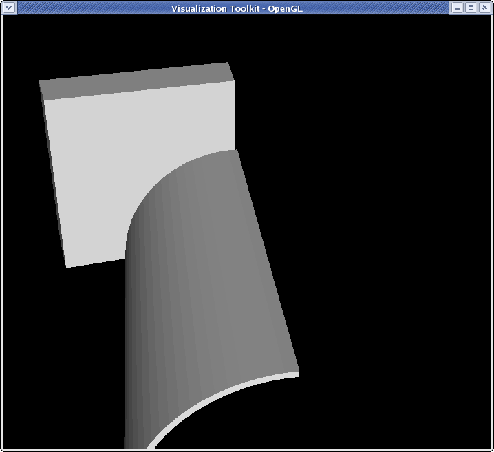 <source lang="python">
- we can see what's going on a little better
>>> clipFilter.UseValueAsOffset = 1
>>> clipFilter.Value = 5
>>> Render()
</source>
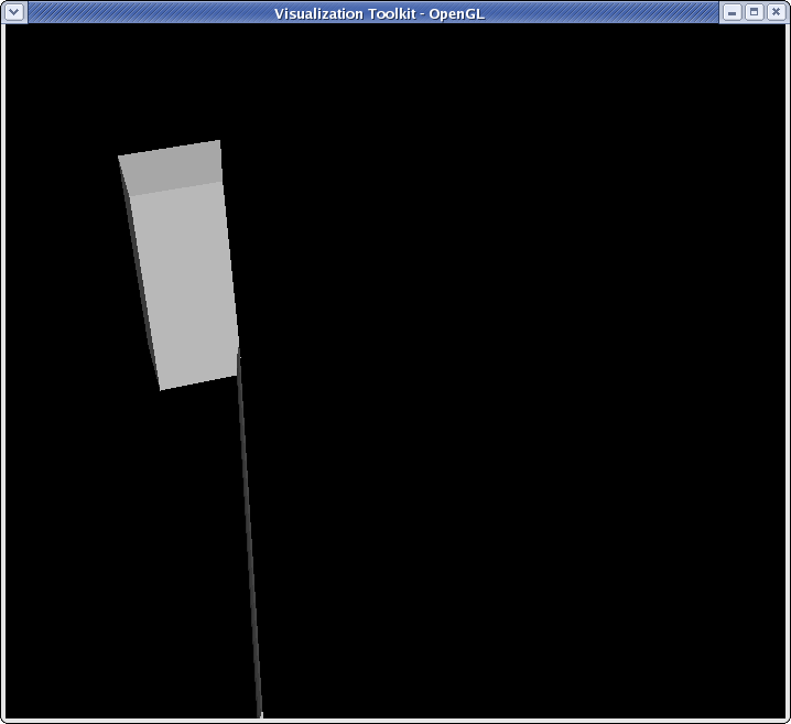 <source lang="python">
- let's change the orientation of the clip filter
>>> clipFilter.ClipType.Normal [1.0, 0.0, 0.0] >>> clipFilter.ClipType.Origin [0.0, 0.0, 0.0]
- reset the offset value of the clip to 0
>>> clipFilter.Value = 0
>>> clipFilter.ClipType.Normal = [0,0,1]
>>> Render()
</source>
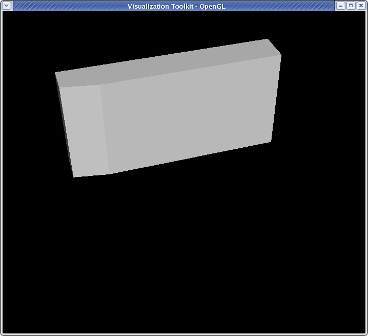 <source lang="python">
>>> clipFilter.Value = -3
>>> Render()
</source>
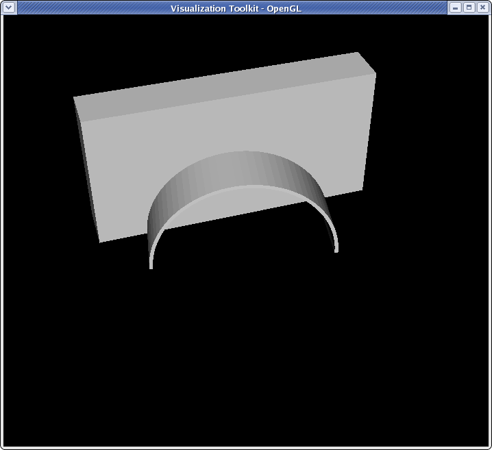 <source lang="python">
>>> clipFilter.InsideOut = 1
>>> Render()
</source>
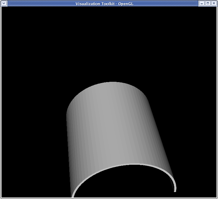
Slice filter
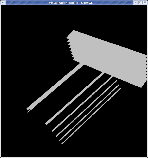
Getting the camera on this one can be right since the slices are invisible from certain angles.
<source lang="python">
>>> from paraview.simple import *
>>> reader = ExodusIIReader(FileName=".../Data/can.ex2")
>>> sliceFilter = Slice(reader)
>>> Show(sliceFilter)
>>> Render()
>>> camera = GetActiveCamera()
>>> camera.Elevation(30)
>>> camera.SetPosition(-51.3152,4.987,-9.64218)
>>> Render()
</source>
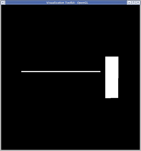 <source lang="python">
>>> sliceFilter.SliceType.Normal
[1.0, 0.0, 0.0]
- the origin of the slice needs to be moved to see slices in the Y-plane
>>> sliceFilter.SliceType.Origin = [2.5,5,0]
>>> sliceFilter.SliceType.Normal = [0,1,0]
>>> Render()
</source>
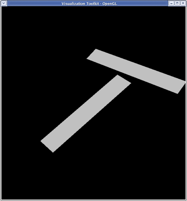 <source lang="python">
>>> sliceFilter.SliceType.Normal = [0,0,1]
>>> Render()
</source>
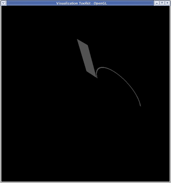 <source lang="python">
>>> sliceFilter.SliceType.Normal = [0,1,0] >>> sliceFilter.SliceOffsetValues [] >>> sliceFilter.SliceOffsetValues = [-4,-3.11,-2.22,-1.33,-0.44,0.44,1.33,2.22,3.11,4] >>> Render()
Glyph filter
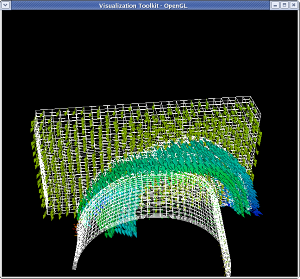
<source lang="python"> >>> from paraview.simple import * >>> reader = ExodusIIReader(FileName=".../Data/can.ex2") >>> Show(reader) >>> camera = GetActiveCamera() >>> camera.SetPosition(0,5,-45) >>> camera.Elevation(30)
- Change the can to be wireframe so we can see the glyphs
>>> dp1 = GetDisplayProperties(reader) >>> dp1.Representation = 'Wireframe'
>>> glyphFilter = Glyph(reader)
- We won't see much if we don't move forward in the animation a little bit
>>> tsteps = reader.TimestepValues >>> view = GetActiveView() >>> view.ViewTime = tsteps[20]
>>> glyphFilter.Vectors ['POINTS', 'DISPL']
- Set the glyphs to use the acceleration vectors and adjust scale factor
>>> glyphFilter.Vectors = 'ACCL'
>>> glyphFilter.SetScaleFactor
1.0
>>> glyphFilter.SetScaleFactor = 0.0000002
</source>
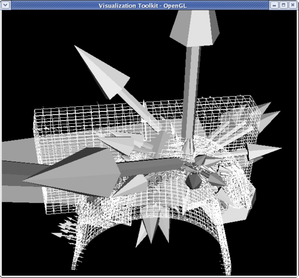 <source lang="python">
- Set the glyphs to use the velocity vectors and adjust scale factor
>>> glyphFilter.Vectors = 'VEL' >>> glyphFilter.SetScaleFactor = 3e-4
- Let's add some color
>>> dp2 = GetDisplayProperties(glyphFilter) >>> glyphFilter.PointData[:] [Array: PedigreeNodeId, Array: DISPL, Array: VEL, Array: ACCL, Array: GlobalNodeId, Array: GlyphVector]
- We'll color by velocity so use that array.
>>> vel = glyphFilter.PointData[2] >>> vel.GetName() 'VEL' >>> vel.GetRange() (-2479.9521484375, 1312.5040283203125) >>> dp2.LookupTable = MakeBlueToRedLT(-2479.9521,1312.5) >>> dp2.ColorAttributeType = 'POINT_DATA' >>> dp2.ColorArrayName = 'VEL' >>> Render()
Threshold filter
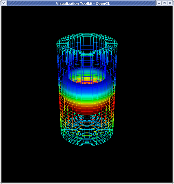
<source lang="python">
>>> from paraview.simple import *
>>> reader = ExodusIIReader(FileName=".../Data/disk_out_ref.ex2")
>>> Show(reader)
>>> dp1 = GetDisplayProperties(reader)
>>> dp1.Representation = 'Wireframe'
>>> camera = GetActiveCamera()
>>> camera.Elevation(-60)
>>> thresholdFilter = Threshold(reader)
>>> thresholdFilter.Scalars
['POINTS', 'GlobalNodeId']
>>> thresholdFilter.Scalars = 'Temp'
>>> Show(thresholdFilter)
>>> thresholdFilter.ThresholdRange
[0.0, 0.0]
>>> thresholdFilter.ThresholdRange = [398.55,913.15]
>>> Render()
</source>
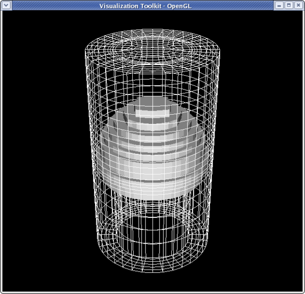 <source lang="python">
>>> dp2 = GetDisplayProperties(thresholdFilter)
>>> thresholdFilter.PointData[:]
[Array: GlobalNodeId, Array: PedigreeNodeId, Array: Temp, Array: V, Array: Pres, Array: AsH3, Array: GaMe3, Array: CH4, Array: H2]
>>> temp = thresholdFilter.PointData[2]
>>> temp.GetRange()
(400.46258544921875, 846.694091796875)
>>> dp2.LookupTable = MakeBlueToRedLT(400.4625,846.6909)
>>> dp2.ColorAttributeType = 'POINT_DATA'
>>> dp2.ColorArrayName = 'Temp'
>>> Render()
</source>
 <source lang="python">
- set the lower threshold to 500
>>> thresholdFilter.ThresholdRange[0] = 500
>>> Render()
</source>
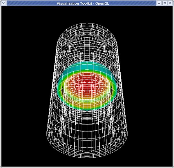 <source lang="python">
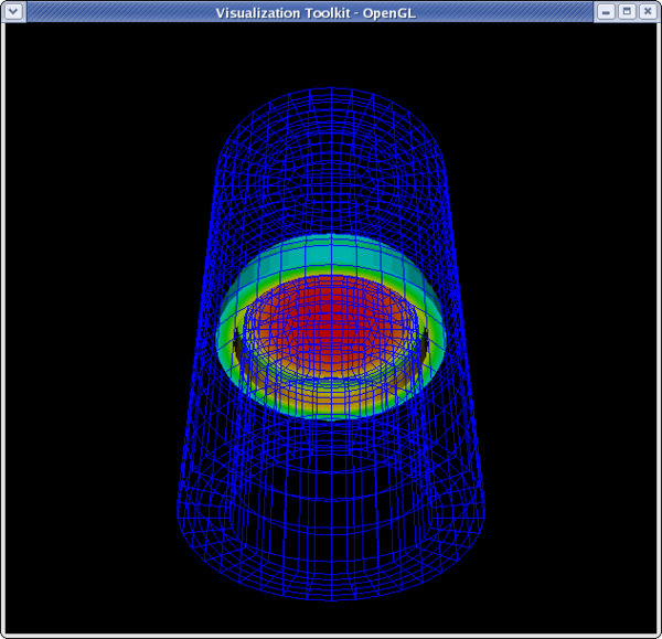
>>> dp1.LookupTable = MakeBlueToRedLT(400.462,84609)
>>> dp1.ColorAttributeType = 'POINT_DATA'
>>> dp1.ColorArrayname = 'Temp'
>>> Render()
</source>
Contour filter
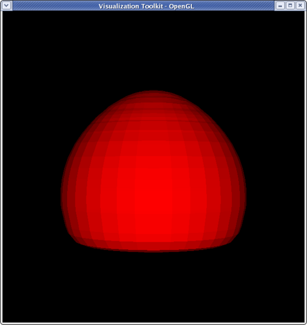
<source lang="python">
>>> from paraview.simple import * >>> reader = ExodusIIReader(FileName = ".../Data/disk_out_ref.ex2") >>> contourFilter = Contour(reader) >>> contourFilter.ContourBy = 'Temp' >>> contourFilter.Isosurfaces [] >>> contourFilter.Isosurfaces = [400] >>> camera = GetActiveCamera() >>> camera.Elevation(-90)
>>> dp2 = GetDisplayProperties(contourFilter) >>> contourFilter.PointData[:] [Array: Temp, Array: V, Array: Pres, Array: AsH3, Array: GaMe3, Array: CH4, Array: H2] >>> temp = contourFilter.PointData[0] >>> temp.GetRange() (399.99999999999994, 400.00000000000006) >>> dp2.LookupTable = MakeBlueToRedLT(399.999,400) >>> dp2.ColorAttributeType = 'POINT_DATA' >>> dp2.ColorArrayName = 'Temp' >>> Render()
</source>
 <source lang="python">
>>> pres = contourFilter.PointData[2] >>> pres.GetRange() (0.0074376024368978605, 0.02845284189526591) >>> dp2.LookupTable = MakeBlueToRedLT(0.007437602,0.02845284) >>> dp2.ColorArrayName = 'Pres'
</source>
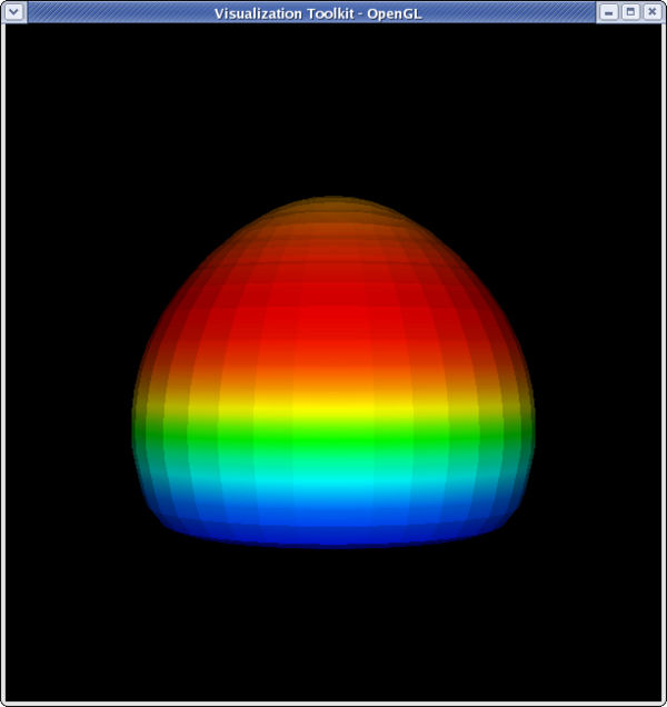 <source lang="python">
>>> dp1 = GetDisplayProperties(reader) >>> dp1.Representation = 'Wireframe' >>> dp1.LookupTable = dp2.LookupTable >>> dp1.ColorAttributeType = 'POINT_DATA' >>> dp1.ColorArrayName = 'Pres' >>> Show(reader)
>>> camera.Dolly(0.5) >>> Render() <paraview.servermanager.RenderView object at 0x14c8ed0> >>> camera.Elevation(-30) >>> Render()
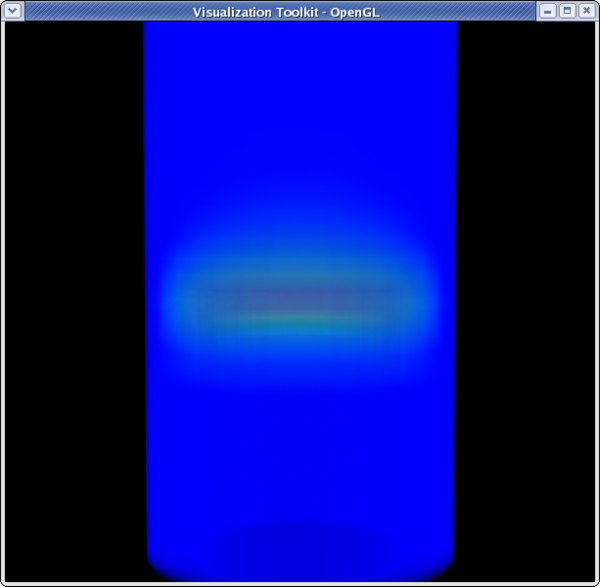
Clip to Scalar filter
<source lang="python"> >>> from paraview.simple import * >>> reader = ExodusIIReader(FileName=".../Data/disk_out_ref.ex2") >>> clipFilter = Clip(reader) >>> clipFilter.ClipType = 'Scalar'
>>> clipFilter.Scalars = 'Temp' >>> clipFilter.Value = 400 >>> Show(clipFilter) >>> camera = GetActiveCamera() >>> camera.Elevation(-90) >>> Render()
</source>
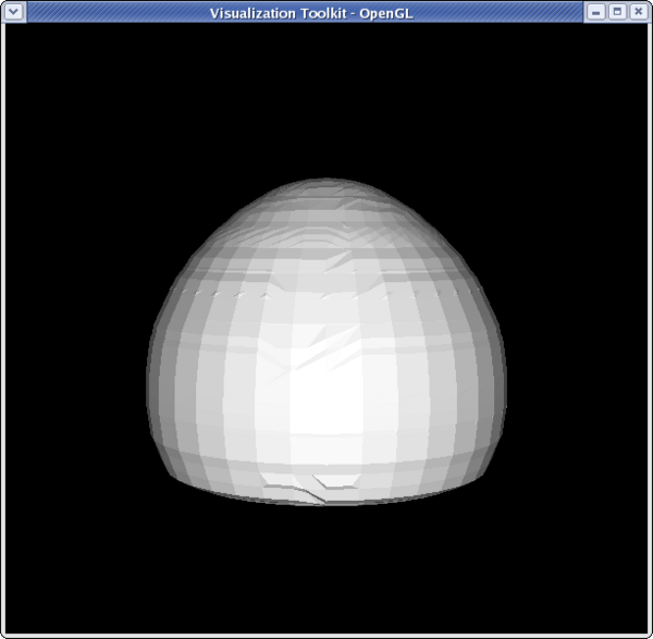 <source lang="python">
>>> clipFilter2 = Clip(clipFilter) >>> Show(clipFilter2) >>> Hide(clipFilter)
>>> camera.SetPosition(-39,0,1.46) >>> camera.Roll(90)
</source>
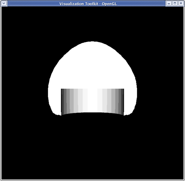 <source lang="python">
>>> dp1 = GetDisplayProperties(reader) >>> dp2 = GetDisplayProperties(clipFilter2) >>> clipFilter2.PointData[:] [Array: Temp, Array: V, Array: Pres, Array: AsH3, Array: GaMe3, Array: CH4, Array: H2] >>> temp = clipFilter2.PointData[0] >>> temp.GetRange() (399.99999999999994, 913.1500244140625) >>> dp2.LookupTable = MakeBlueToRedLT(400,913.15) >>> dp2.ColorAttributeType = 'POINT_DATA' >>> dp2.ColorArrayName = 'Temp' >>> Hide(reader) >>> Render()
</source>
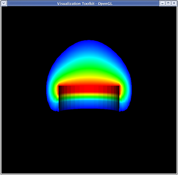 <source lang="python">
>>> dp1.Representation = 'Volume' >>> temp.GetRange() (399.99999999999994, 913.1500244140625) >>> dp1.LookupTable = dp2.LookupTable >>> dp1.ColorAttributeType = 'POINT_DATA' >>> dp1.ColorArrayName = 'Temp' >>> Render()
Cell to Point/ Point to Cell filters
These filters are used to convert a data set from being cell data to being point data and vice versa. This is sometimes useful if a filter requires one type of data, and a user only has the other type of data. An example would be using can.exo. You cannot get a contour of EQPS directly, since EQPS is cell data and contour only works on points. Use filter Cell Data to Point Data first, then call contour.
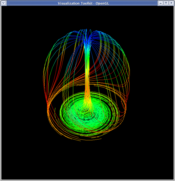
Stream Tracer
<source lang="python">
>>> from paraview.simple import * >>> reader = ExodusIIReader(FileName=".../Data/disk_out_ref.ex2") >>> streamTracer = StreamTracer(reader) >>> streamTracer.Vectors = 'V' >>> streamTracer.SeedType.NumberOfPoints = 100 >>> streamTracer.SeedType.Radius = 1.15 >>> streamTracer.SetPropertyWithName('Max.Propagation',20.1599) >>> Show(streamTracer) >>> camera = GetActiveCamera() >>> camera.Elevation(-45) >>> camera.Dolly(0.4) >>> dp1 = GetDisplayProperties(streamTracer) >>> streamTracer.PointData[:] [Array: Temp, Array: V, Array: Pres, Array: AsH3, Array: GaMe3, Array: CH4, Array: H2, Array: IntegrationTime, Array: Vorticity, Array: Rotation, Array: AngularVelocity, Array: Normals] >>> pres = streamTracer.PointData[2] >>> dp1.LookupTable = MakeBlueToRedLT(pres.GetRange()[0],pres.GetRange()[1]) >>> dp1.ColorAttributeType = 'POINT_DATA' >>> dp1.ColorArrayName = 'Pres'
>>> Render()
Calculator filter
Coming soon.
Acknowledgements
Sandia is a multiprogram laboratory operated by Sandia Corporation, a Lockheed Martin Company, for the United States Department of Energy’s National Nuclear Security Administration under contract DE-AC04-94AL85000.
