Figure 8.1: Relationship between DataObject and ProcessObject.
This purpose of this chapter is help developers create their own filter (process object). This chapter is divided into four major parts. An initial definition of terms is followed by an overview of the filter creation process. Next, data streaming is discussed. The way data is streamed in ITK must be understood in order to write correct filters. Finally, a section on multi-threading describes what you must do in order to take advantage of shared memory parallel processing.
The following is some basic terminology for the discussion that follows. Chapter 3 provides additional background information.
Figure 8.1: Relationship between DataObject and
ProcessObject.
Filters are defined with respect to the type of data they input (if any), and the type of data they output (if any). The key to writing a ITK filter is to identify the number and types of input and output. Having done so, there are often superclasses that simplify this task via class derivation. For example, most filters in ITK take a single image as input, and produce a single image on output. The superclass itk::ImageToImageFilter is a convenience class that provide most of the functionality needed for such a filter.
Some common base classes for new filters include:
Once the appropriate superclass is identified, the filter writer implements the class defining the methods required by most all ITK objects: New(), PrintSelf(), and protected constructor, copy constructor, delete, and operator=, and so on. Also, don’t forget standard type aliases like Self, Superclass, Pointer, and ConstPointer. Then the filter writer can focus on the most important parts of the implementation: defining the API, data members, and other implementation details of the algorithm. In particular, the filter writer will have to implement either a GenerateData() (non-threaded) or ThreadedGenerateData() and DynamicThreadedGenerateData() methods. (See Section 3.2.7 for an overview of multi-threading in ITK.)
An important note: the GenerateData() method is required to allocate memory for the output. The ThreadedGenerateData() method is not. In default implementation (see itk::ImageSource, a superclass of itk::ImageToImageFilter) GenerateData() allocates memory and then invokes DynamicThreadedGenerateData() or ThreadedGenerateData().
One of the most important decisions that the developer must make is whether the filter can stream data; that is, process just a portion of the input to produce a portion of the output. Often superclass behavior works well: if the filter processes the input using single pixel access, then the default behavior is adequate. If not, then the user may have to a) find a more specialized superclass to derive from, or b) override one or more methods that control how the filter operates during pipeline execution. The next section describes these methods.
The data associated with multi-dimensional images is large and becoming larger. This trend is due to advances in scanning resolution, as well as increases in computing capability. Any practical segmentation and registration software system must address this fact in order to be useful in application. ITK addresses this problem via its data streaming facility.
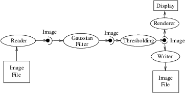
In ITK, streaming is the process of dividing data into pieces, or regions, and then processing this data through the data pipeline. Recall that the pipeline consists of process objects that generate data objects, connected into a pipeline topology. The input to a process object is a data object (unless the process initiates the pipeline and then it is a source process object). These data objects in turn are consumed by other process objects, and so on, until a directed graph of data flow is constructed. Eventually the pipeline is terminated by one or more mappers, that may write data to storage, or interface with a graphics or other system. This is illustrated in figures 8.1 and 8.2.
A significant benefit of this architecture is that the relatively complex process of managing pipeline execution is designed into the system. This means that keeping the pipeline up to date, executing only those portions of the pipeline that have changed, multi-threading execution, managing memory allocation, and streaming is all built into the architecture. However, these features do introduce complexity into the system, the bulk of which is seen by class developers. The purpose of this chapter is to describe the pipeline execution process in detail, with a focus on data streaming.
The pipeline execution process performs several important functions.
To perform these functions, the execution process negotiates with the filters that define the pipeline. Only each filter can know how much data is required on input to produce a particular output. For example, a shrink filter with a shrink factor of two requires an image twice as large (in terms of its x-y dimensions) on input to produce a particular size output. An image convolution filter would require extra input (boundary padding) depending on the size of the convolution kernel. Some filters require the entire input to produce an output (for example, a histogram), and have the option of requesting the entire input. (In this case streaming does not work unless the developer creates a filter that can request multiple pieces, caching state between each piece to assemble the final output.)
Ultimately the negotiation process is controlled by the request for data of a particular size (i.e., region). It may be that the user asks to process a region of interest within a large image, or that memory limitations result in processing the data in several pieces. For example, an application may compute the memory required by a pipeline, and then use itk::StreamingImageFilter to break the data processing into several pieces. The data request is propagated through the pipeline in the upstream direction, and the negotiation process configures each filter to produce output data of a particular size.
The secret to creating a streaming filter is to understand how this negotiation process works, and how to override its default behavior by using the appropriate virtual functions defined in itk::ProcessObject. The next section describes the specifics of these methods, and when to override them. Examples are provided along the way to illustrate concepts.
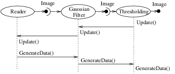
Typically pipeline execution is initiated when a process object receives the ProcessObject::Update() method invocation. This method is simply delegated to the output of the filter, invoking the DataObject::Update() method. Note that this behavior is typical of the interaction between ProcessObject and DataObject: a method invoked on one is eventually delegated to the other. In this way the data request from the pipeline is propagated upstream, initiating data flow that returns downstream.
The DataObject::Update() method in turn invokes three other methods:
The UpdateOutputInformation() method first calls the VerifyPreconditions to check that all required inputs are set and all parameters are valid and consistent. This enables quick failure of a filter when not configure correctly. The default implementation checks that all required pipeline inputs are set.
Next the pipeline modified time is determined. The RequestedRegion is set to process all the data, i.e., the LargestPossibleRegion, if neither UpdateLargestPossibleRegion was called nor RequestedRegion has not been set. The UpdateOutputInformation() propagates upstream through the entire pipeline and terminates at the sources.
After the upstream inputs have completed their UpdateOutputInformation the metadata of inputs are available. The VerifyInputInformation is then called. The default implementation in ImageToImageFilter checks that all input images occupy the same physical space. This may need to be overridden if the filter does not require the image’s voxels occupy the same physical space.
During UpdateOutputInformation(), filters have a chance to override the ProcessObject::GenerateOutputInformation() method (GenerateOutputInformation() is invoked by UpdateOutputInformation()). The default behavior is for the GenerateOutputInformation() to copy the metadata describing the input to the output (via DataObject::CopyInformation()). Remember, information is metadata describing the output, such as the origin, spacing, and LargestPossibleRegion (i.e., largest possible size) of an image.
A good example of this behavior is itk::ShrinkImageFilter. This filter takes an input image and shrinks it by some integral value. The result is that the spacing and LargestPossibleRegion of the output will be different to that of the input. Thus, GenerateOutputInformation() is overloaded.
The PropagateRequestedRegion() call propagates upstream to satisfy a data request. In typical application this data request is usually the LargestPossibleRegion, but if streaming is necessary, or the user is interested in updating just a portion of the data, the RequestedRegion may be any valid region within the LargestPossibleRegion.
The function of PropagateRequestedRegion() is, given a request for data (the amount is specified by RequestedRegion), propagate upstream configuring the filter’s input and output process object’s to the correct size. Eventually, this means configuring the BufferedRegion, that is the amount of data actually allocated.
The reason for the buffered region is this: the output of a filter may be consumed by more than one downstream filter. If these consumers each request different amounts of input (say due to kernel requirements or other padding needs), then the upstream, generating filter produces the data to satisfy both consumers, that may mean it produces more data than one of the consumers needs.
The ProcessObject::PropagateRequestedRegion() method invokes three methods that the filter developer may choose to overload.
itk::RGBGibbsPriorFilter is an example of a filter that needs to invoke EnlargeOutputRequestedRegion(). The designer of this filter decided that the filter should operate on all the data. Note that a subtle interplay between this method and GenerateInputRequestedRegion() is occurring here. The default behavior of GenerateInputRequestedRegion() (at least for itk::ImageToImageFilter) is to set the input RequestedRegion to the output’s ReqestedRegion. Hence, by overriding the method EnlargeOutputRequestedRegion() to set the output to the LargestPossibleRegion, effectively sets the input to this filter to the LargestPossibleRegion (and probably causing all upstream filters to process their LargestPossibleRegion as well. This means that the filter, and therefore the pipeline, does not stream. This could be fixed by reimplementing the filter with the notion of streaming built in to the algorithm.)
itk::GradientMagnitudeImageFilter is an example of a filter that needs to invoke GenerateInputRequestedRegion(). It needs a larger input requested region because a kernel is required to compute the gradient at a pixel. Hence the input needs to be “padded out” so the filter has enough data to compute the gradient at each output pixel.
UpdateOutputData() is the third and final method as a result of the Update() method. The purpose of this method is to determine whether a particular filter needs to execute in order to bring its output up to date. (A filter executes when its GenerateData() method is invoked.) Filter execution occurs when a) the filter is modified as a result of modifying an instance variable; b) the input to the filter changes; c) the input data has been released; or d) an invalid RequestedRegion was set previously and the filter did not produce data. Filters execute in order in the downstream direction. Once a filter executes, all filters downstream of it must also execute.
DataObject::UpdateOutputData() is delegated to the DataObject’s source (i.e., the ProcessObject that generated it) only if the DataObject needs to be updated. A comparison of modified time, pipeline time, release data flag, and valid requested region is made. If any one of these conditions indicate that the data needs regeneration, then the source’s ProcessObject::UpdateOutputData() is invoked. These calls are made recursively up the pipeline until a source filter object is encountered, or the pipeline is determined to be up to date and valid. At this point, the recursion unrolls, and the execution of the filter proceeds. (This means that the output data is initialized, StartEvent is invoked, the filters GenerateData() is called, EndEvent is invoked, and input data to this filter may be released, if requested. In addition, this filter’s InformationTime is updated to the current time.)
The developer will never override UpdateOutputData(). The developer need only write the GenerateData() method (non-threaded) or DynamicThreadedGenerateData() method. A discussion on threading follows in the next section.
Filters that can process data in pieces can typically multi-process using the data parallel, shared memory implementation built into the pipeline execution process. To create a multi-threaded filter, simply define and implement a DynamicThreadedGenerateData(). For example, a itk::ImageToImageFilter would create the method:
The key to threading is to generate output for the output region given as the parameter. In ITK, this is simple to do because an output iterator can be created using the region provided. Hence the output can be iterated over, accessing the corresponding input pixels as necessary to compute the value of the output pixel.
Multi-threading requires caution when performing I/O (including using cout or cerr) or invoking events. A safe practice is to allow only the invoking thread to perform I/O or generate events. If more than one thread tries to write to the same place at the same time, the program can behave badly, and possibly even deadlock or crash.
DynamicThreadedGenerateData signature allows number of pieces (output regions) to be processed to be different, usually bigger than the number of real threads executing the work. In turn, this allows load balancing. The number of work units controls filter parallelism, and the name ‘threads’ is reserved for real threads as exposed by itk::MultiThreaderBase and its descendants.
In order to fully participate in the ITK pipeline, filters are expected to follow certain conventions, and provide certain interfaces. This section describes the minimum requirements for a filter to integrate into the ITK framework.
A filter should define public types for the class itself (Self) and its Superclass, and const and non-const smart pointers, thus:
The Pointer type is particularly useful, as it is a smart pointer that will be used by all client code to hold a reference-counted instantiation of the filter.
Once the above types have been defined, you can use the following convenience macros, which permit your filter to participate in the object factory mechanism, and to be created using the canonical ::New():
The default constructor should be protected, and provide sensible defaults (usually zero) for all parameters. The copy constructor and assignment operator should not implemented in order to prevent instantiating the filter without the factory methods (above). They should be declared in the public section using the ITK_DISALLOW_COPY_AND_ASSIGN macro (see Section ?? on page ??).
Finally, the template implementation code (in the .hxx file) should be included, bracketed by a test for manual instantiation, thus:
A filter can be printed to an std::ostream (such as std::cout) by implementing the following method:
and writing the name-value pairs of the filter parameters to the supplied output stream. This is particularly useful for debugging.
Many convenience macros are provided by ITK, to simplify filter coding. Some of these are described below:
Much more useful information can be learned from browsing the source in Code/Common/itkMacro.h and for the itk::Object and itk::LightObject classes.
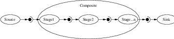
In general, most ITK filters implement one particular algorithm, whether it be image filtering, an information metric, or a segmentation algorithm. In the previous section, we saw how to write new filters from scratch. However, it is often very useful to be able to make a new filter by combining two or more existing filters, which can then be used as a building block in a complex pipeline. This approach follows the Composite pattern [?], whereby the composite filter itself behaves just as a regular filter, providing its own (potentially higher level) interface and using other filters (whose detail is hidden to users of the class) for the implementation. This composite structure is shown in Figure 8.4, where the various Stage-n filters are combined into one by the Composite filter. The Source and Sink filters only see the interface published by the Composite. Using the Composite pattern, a composite filter can encapsulate a pipeline of arbitrary complexity. These can in turn be nested inside other pipelines.
There are a few considerations to take into account when implementing a composite filter. All the usual requirements for filters apply (as discussed above), but the following guidelines should be considered:
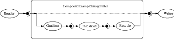
This grafting process is illustrated in Figure 8.5.
The source code for this section can be found in the file
CompositeFilterExample.cxx.
The composite filter we will build combines three filters: a gradient magnitude operator, which will calculate the first-order derivative of the image; a thresholding step to select edges over a given strength; and finally a rescaling filter, to ensure the resulting image data is visible by scaling the intensity to the full spectrum of the output image type.
Since this filter takes an image and produces another image (of identical type), we will specialize the ImageToImageFilter:
Next we include headers for the component filters:
Now we can declare the filter itself. It is within the ITK namespace, and we decide to make it use the same image type for both input and output, so that the template declaration needs only one parameter. Deriving from ImageToImageFilter provides default behavior for several important aspects, notably allocating the output image (and making it the same dimensions as the input).
Next we have the standard declarations, used for object creation with the object factory:
Here we declare an alias (to save typing) for the image’s pixel type, which determines the type of the threshold value. We then use the convenience macros to define the Get and Set methods for this parameter.
Now we can declare the component filter types, templated over the enclosing image type:
The component filters are declared as data members, all using the smart pointer types.
The constructor sets up the pipeline, which involves creating the stages, connecting them together, and setting default parameters.
template< typename TImage >
CompositeExampleImageFilter< TImage >
::CompositeExampleImageFilter()
{
m_Threshold = 1;
m_GradientFilter = GradientType::New();
m_ThresholdFilter = ThresholdType::New();
m_ThresholdFilter->SetInput( m_GradientFilter->GetOutput() );
m_RescaleFilter = RescalerType::New();
m_RescaleFilter->SetInput( m_ThresholdFilter->GetOutput() );
m_RescaleFilter->SetOutputMinimum(
NumericTraits<PixelType>::NonpositiveMin());
m_RescaleFilter->SetOutputMaximum(NumericTraits<PixelType>::max());
}
The GenerateData() is where the composite magic happens.
First, connect the first component filter to the inputs of the composite filter (the actual input, supplied by the upstream stage). At a filter’s GenerateData() stage, the input image’s information and pixel buffer content have been updated by the pipeline. To prevent the mini-pipeline update from propagating upstream, the input image is disconnected from the pipeline by grafting its contents to a new itk::Image pointer.
This implies that the composite filter must implement pipeline methods that indicate the itk::ImageRegion’s it requires and generates, like GenerateInputRequestedRegion(), GenerateOutputRequestedRegion(), GenerateOutputInformation() and EnlargeOutputRequestedRegion(), according to the behavior of its component filters.
Next, graft the output of the last stage onto the output of the composite, which ensures the requested region is updated and the last stage populates the output buffer allocated by the composite filter. We force the composite pipeline to be processed by calling Update() on the final stage. Then, graft the output back onto the output of the enclosing filter, so it has the result available to the downstream filter.
template< typename TImage >
void
CompositeExampleImageFilter< TImage >
::GenerateData()
{
typename ImageType::Pointer input = ImageType::New();
input->Graft( const_cast< ImageType ⋆ >( this->GetInput() ));
m_GradientFilter->SetInput( input );
m_ThresholdFilter->ThresholdBelow( this->m_Threshold );
m_RescaleFilter->GraftOutput( this->GetOutput() );
m_RescaleFilter->Update();
this->GraftOutput( m_RescaleFilter->GetOutput() );
}
Finally we define the PrintSelf method, which (by convention) prints the filter parameters. Note how it invokes the superclass to print itself first, and also how the indentation prefixes each line.
It is important to note that in the above example, none of the internal details of the pipeline were exposed to users of the class. The interface consisted of the Threshold parameter (which happened to change the value in the component filter) and the regular ImageToImageFilter interface. This example pipeline is illustrated in Figure 8.5.