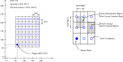
Figure 4.1: Geometrical concepts associated with the ITK image.
This chapter introduces the basic classes responsible for representing data in ITK. The most common classes are itk::Image, itk::Mesh and itk::PointSet.
The itk::Image class follows the spirit of Generic Programming, where types are separated from the algorithmic behavior of the class. ITK supports images with any pixel type and any spatial dimension.
The source code for this section can be found in the file
Image1.cxx.
This example illustrates how to manually construct an itk::Image class. The following is the minimal code needed to instantiate, declare and create the Image class.
First, the header file of the Image class must be included.
Then we must decide with what type to represent the pixels and what the dimension of the image will be. With these two parameters we can instantiate the Image class. Here we create a 3D image with unsigned short pixel data.
The image can then be created by invoking the New() operator from the corresponding image type and assigning the result to a itk::SmartPointer.
In ITK, images exist in combination with one or more regions. A region is a subset of the image and indicates a portion of the image that may be processed by other classes in the system. One of the most common regions is the LargestPossibleRegion, which defines the image in its entirety. Other important regions found in ITK are the BufferedRegion, which is the portion of the image actually maintained in memory, and the RequestedRegion, which is the region requested by a filter or other class when operating on the image.
In ITK, manually creating an image requires that the image is instantiated as previously shown, and that regions describing the image are then associated with it.
A region is defined by two classes: the itk::Index and itk::Size classes. The origin of the region within the image is defined by the Index. The extent, or size, of the region is defined by the Size. When an image is created manually, the user is responsible for defining the image size and the index at which the image grid starts. These two parameters make it possible to process selected regions.
The Index is represented by a n-dimensional array where each component is an integer indicating—in topological image coordinates—the initial pixel of the image.
The region size is represented by an array of the same dimension as the image (using the itk::Size class). The components of the array are unsigned integers indicating the extent in pixels of the image along every dimension.
Having defined the starting index and the image size, these two parameters are used to create an itk::ImageRegion object which basically encapsulates both concepts. The region is initialized with the starting index and size of the image.
Finally, the region is passed to the Image object in order to define its extent and origin. The SetRegions method sets the LargestPossibleRegion, BufferedRegion, and RequestedRegion simultaneously. Note that none of the operations performed to this point have allocated memory for the image pixel data. It is necessary to invoke the Allocate() method to do this. Allocate does not require any arguments since all the information needed for memory allocation has already been provided by the region.
In practice it is rare to allocate and initialize an image directly. Images are typically read from a source, such a file or data acquisition hardware. The following example illustrates how an image can be read from a file.
The source code for this section can be found in the file
Image2.cxx.
The first thing required to read an image from a file is to include the header file of the itk::ImageFileReader class.
Then, the image type should be defined by specifying the type used to represent pixels and the dimensions of the image.
Using the image type, it is now possible to instantiate the image reader class. The image type is used as a template parameter to define how the data will be represented once it is loaded into memory. This type does not have to correspond exactly to the type stored in the file. However, a conversion based on C-style type casting is used, so the type chosen to represent the data on disk must be sufficient to characterize it accurately. Readers do not apply any transformation to the pixel data other than casting from the pixel type of the file to the pixel type of the ImageFileReader. The following illustrates a typical instantiation of the ImageFileReader type.
The reader type can now be used to create one reader object. A itk::SmartPointer (defined by the ::Pointer notation) is used to receive the reference to the newly created reader. The New() method is invoked to create an instance of the image reader.
The minimal information required by the reader is the filename of the image to be loaded in memory. This is provided through the SetFileName() method. The file format here is inferred from the filename extension. The user may also explicitly specify the data format using the itk::ImageIOBase class (a list of possibilities can be found in the inheritance diagram of this class.).
Reader objects are referred to as pipeline source objects; they respond to pipeline update requests and initiate the data flow in the pipeline. The pipeline update mechanism ensures that the reader only executes when a data request is made to the reader and the reader has not read any data. In the current example we explicitly invoke the Update() method because the output of the reader is not connected to other filters. In normal application the reader’s output is connected to the input of an image filter and the update invocation on the filter triggers an update of the reader. The following line illustrates how an explicit update is invoked on the reader.
Access to the newly read image can be gained by calling the GetOutput() method on the reader. This method can also be called before the update request is sent to the reader. The reference to the image will be valid even though the image will be empty until the reader actually executes.
Any attempt to access image data before the reader executes will yield an image with no pixel data. It is likely that a program crash will result since the image will not have been properly initialized.
The source code for this section can be found in the file
Image3.cxx.
This example illustrates the use of the SetPixel() and GetPixel() methods. These two methods provide direct access to the pixel data contained in the image. Note that these two methods are relatively slow and should not be used in situations where high-performance access is required. Image iterators are the appropriate mechanism to efficiently access image pixel data. (See Chapter 6 on page 185 for information about image iterators.)
The individual position of a pixel inside the image is identified by a unique index. An index is an array of integers that defines the position of the pixel along each dimension of the image. The IndexType is automatically defined by the image and can be accessed using the scope operator itk::Index. The length of the array will match the dimensions of the associated image.
The following code illustrates the declaration of an index variable and the assignment of values to each of its components. Please note that no SmartPointer is used to access the Index. This is because Index is a lightweight object that is not intended to be shared between objects. It is more efficient to produce multiple copies of these small objects than to share them using the SmartPointer mechanism.
The following lines declare an instance of the index type and initialize its content in order to associate it with a pixel position in the image.
Having defined a pixel position with an index, it is then possible to access the content of the pixel in the image. The GetPixel() method allows us to get the value of the pixels.
The SetPixel() method allows us to set the value of the pixel.
Please note that GetPixel() returns the pixel value using copy and not reference semantics. Hence, the method cannot be used to modify image data values.
Remember that both SetPixel() and GetPixel() are inefficient and should only be used for debugging or for supporting interactions like querying pixel values by clicking with the mouse.
The source code for this section can be found in the file
Image4.cxx.
Even though ITK can be used to perform general image processing tasks, the primary purpose of the toolkit is the processing of medical image data. In that respect, additional information about the images is considered mandatory. In particular the information associated with the physical spacing between pixels and the position of the image in space with respect to some world coordinate system are extremely important.
Image origin, voxel directions (i.e. orientation), and spacing are fundamental to many applications. Registration, for example, is performed in physical coordinates. Improperly defined spacing, direction, and origins will result in inconsistent results in such processes. Medical images with no spatial information should not be used for medical diagnosis, image analysis, feature extraction, assisted radiation therapy or image guided surgery. In other words, medical images lacking spatial information are not only useless but also hazardous.
Figure 4.1 illustrates the main geometrical concepts associated with the itk::Image. In this figure, circles are used to represent the center of pixels. The value of the pixel is assumed to exist as a Dirac delta function located at the pixel center. Pixel spacing is measured between the pixel centers and can be different along each dimension. The image origin is associated with the coordinates of the first pixel in the image. For this simplified example, the voxel lattice is perfectly aligned with physical space orientation, and the image direction is therefore an identity mapping. If the voxel lattice samples were rotated with respect to physical space, then the image direction would contain a rotation matrix.
A pixel is considered to be the rectangular region surrounding the pixel center holding the data value.
Image spacing is represented in a FixedArray whose size matches the dimension of the image. In order to manually set the spacing of the image, an array of the corresponding type must be created. The elements of the array should then be initialized with the spacing between the centers of adjacent pixels. The following code illustrates the methods available in the itk::Image class for dealing with spacing and origin.
The array can be assigned to the image using the SetSpacing() method.
The spacing information can be retrieved from an image by using the GetSpacing() method. This method returns a reference to a FixedArray. The returned object can then be used to read the contents of the array. Note the use of the const keyword to indicate that the array will not be modified.
The image origin is managed in a similar way to the spacing. A Point of the appropriate dimension must first be allocated. The coordinates of the origin can then be assigned to every component. These coordinates correspond to the position of the first pixel of the image with respect to an arbitrary reference system in physical space. It is the user’s responsibility to make sure that multiple images used in the same application are using a consistent reference system. This is extremely important in image registration applications.
The following code illustrates the creation and assignment of a variable suitable for initializing the image origin.
The origin can also be retrieved from an image by using the GetOrigin() method. This will return a reference to a Point. The reference can be used to read the contents of the array. Note again the use of the const keyword to indicate that the array contents will not be modified.
The image direction matrix represents the orientation relationships between the image samples and physical space coordinate systems. The image direction matrix is an orthonormal matrix that describes the possible permutation of image index values and the rotational aspects that are needed to properly reconcile image index organization with physical space axis. The image directions is a NxN matrix where N is the dimension of the image. An identity image direction indicates that increasing values of the 1st, 2nd, 3rd index element corresponds to increasing values of the 1st, 2nd and 3rd physical space axis respectively, and that the voxel samples are perfectly aligned with the physical space axis.
The following code illustrates the creation and assignment of a variable suitable for initializing the image direction with an identity.
The direction can also be retrieved from an image by using the GetDirection() method. This will return a reference to a Matrix. The reference can be used to read the contents of the array. Note again the use of the const keyword to indicate that the matrix contents can not be modified.
Once the spacing, origin, and direction of the image samples have been initialized, the image will correctly map pixel indices to and from physical space coordinates. The following code illustrates how a point in physical space can be mapped into an image index for the purpose of reading the content of the closest pixel.
First, a itk::Point type must be declared. The point type is templated over the type used to represent coordinates and over the dimension of the space. In this particular case, the dimension of the point must match the dimension of the image.
The itk::Point class, like an itk::Index, is a relatively small and simple object. This means that no itk::SmartPointer is used here and the objects are simply declared as instances, like any other C++ class. Once the point is declared, its components can be accessed using traditional array notation. In particular, the [] operator is available. For efficiency reasons, no bounds checking is performed on the index used to access a particular point component. It is the user’s responsibility to make sure that the index is in the range {0,Dimension-1}.
The image will map the point to an index using the values of the current spacing and origin. An index object must be provided to receive the results of the mapping. The index object can be instantiated by using the IndexType defined in the image type.
The TransformPhysicalPointToIndex() method of the image class will compute the pixel index closest to the point provided. The method checks for this index to be contained inside the current buffered pixel data. The method returns a boolean indicating whether the resulting index falls inside the buffered region or not. The output index should not be used when the returned value of the method is false.
The following lines illustrate the point to index mapping and the subsequent use of the pixel index for accessing pixel data from the image.
Remember that GetPixel() and SetPixel() are very inefficient methods for accessing pixel data. Image iterators should be used when massive access to pixel data is required.
The following example illustrates the mathematical relationships between image index locations and its corresponding physical point representation for a given Image.
Let us imagine that a graphical user interface exists where the end user manually selects the voxel index location of the left eye in a volume with a mouse interface. We need to convert that index location to a physical location so that laser guided surgery can be accurately performed. The TransformIndexToPhysicalPoint method can be used for this.
For a given index  in 3D, the physical location
  is calculated as following:
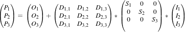 | (4.1) |
Where: : image space index.
 : resulting physical space position of the image index
  .
. : physical space origin of the first image index.
 : direction cosines matrix (orthonormal). It represents the orientation relationship between the image and
the physical space coordinate system.
: direction cosines matrix (orthonormal). It represents the orientation relationship between the image and
the physical space coordinate system. : physical spacing between pixels of the same axis.
The operation can be thought as a particular case of the linear transform:
 | (4.2) |
where  :
:
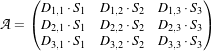 | (4.3) |
In matlab syntax the conversions are:
A corresponding mathematical expansion of the C/C++ code is:
using MatrixType = itk::Matrix<double, Dimension, Dimension>;
MatrixType SpacingMatrix;
SpacingMatrix.Fill( 0.0F );
const ImageType::SpacingType & ImageSpacing = image->GetSpacing();
SpacingMatrix( 0,0 ) = ImageSpacing[0];
SpacingMatrix( 1,1 ) = ImageSpacing[1];
SpacingMatrix( 2,2 ) = ImageSpacing[2];
const ImageType::DirectionType & ImageDirectionCosines =
image->GetDirection();
const ImageType::PointType &ImageOrigin = image->GetOrigin();
using VectorType = itk::Vector< double, Dimension >;
VectorType LeftEyeIndexVector;
LeftEyeIndexVector[0]= LeftEyeIndex[0];
LeftEyeIndexVector[1]= LeftEyeIndex[1];
LeftEyeIndexVector[2]= LeftEyeIndex[2];
ImageType::PointType LeftEyePointByHand =
ImageOrigin + ImageDirectionCosines ⋆ SpacingMatrix ⋆ LeftEyeIndexVector;
The term RGB (Red, Green, Blue) stands for a color representation commonly used in digital imaging. RGB is a representation of the human physiological capability to analyze visual light using three spectral-selective sensors [?, ?]. The human retina possess different types of light sensitive cells. Three of them, known as cones, are sensitive to color [?] and their regions of sensitivity loosely match regions of the spectrum that will be perceived as red, green and blue respectively. The rods on the other hand provide no color discrimination and favor high resolution and high sensitivity.1 A fifth type of receptors, the ganglion cells, also known as circadian2 receptors are sensitive to the lighting conditions that differentiate day from night. These receptors evolved as a mechanism for synchronizing the physiology with the time of the day. Cellular controls for circadian rythms are present in every cell of an organism and are known to be exquisitively precise [?].
The RGB space has been constructed as a representation of a physiological response to light by the three types of cones in the human eye. RGB is not a Vector space. For example, negative numbers are not appropriate in a color space because they will be the equivalent of “negative stimulation” on the human eye. In the context of colorimetry, negative color values are used as an artificial construct for color comparison in the sense that
 | (4.4) |
is just a way of saying that we can produce ColorB by combining ColorA and ColorC. However, we must be aware that (at least in emitted light) it is not possible to subtract light. So when we mention Equation 4.4 we actually mean
 | (4.5) |
On the other hand, when dealing with printed color and with paint, as opposed to emitted light like in computer screens, the physical behavior of color allows for subtraction. This is because strictly speaking the objects that we see as red are those that absorb all light frequencies except those in the red section of the spectrum [?].
The concept of addition and subtraction of colors has to be carefully interpreted. In fact, RGB has a different definition regarding whether we are talking about the channels associated to the three color sensors of the human eye, or to the three phosphors found in most computer monitors or to the color inks that are used for printing reproduction. Color spaces are usually non linear and do not even from a group. For example, not all visible colors can be represented in RGB space [?].
ITK introduces the itk::RGBPixel type as a support for representing the values of an RGB color space. As such, the RGBPixel class embodies a different concept from the one of an itk::Vector in space. For this reason, the RGBPixel lacks many of the operators that may be naively expected from it. In particular, there are no defined operations for subtraction or addition.
When you intend to find the “Mean” of two RGBType pixels, you are assuming that the color in the visual “middle” of the two input pixels can be calculated through a linear operation on their numerical representation. This is unfortunately not the case in color spaces due to the fact that they are based on a human physiological response [?].
If you decide to interpret RGB images as simply three independent channels then you should rather use the itk::Vector type as pixel type. In this way, you will have access to the set of operations that are defined in Vector spaces. The current implementation of the RGBPixel in ITK presumes that RGB color images are intended to be used in applications where a formal interpretation of color is desired, therefore only the operations that are valid in a color space are available in the RGBPixel class.
The following example illustrates how RGB images can be represented in ITK.
The source code for this section can be found in the file
RGBImage.cxx.
Thanks to the flexibility offered by the Generic Programming style on which ITK is based, it is possible to instantiate images of arbitrary pixel type. The following example illustrates how a color image with RGB pixels can be defined.
A class intended to support the RGB pixel type is available in ITK. You could also define your own pixel class and use it to instantiate a custom image type. In order to use the itk::RGBPixel class, it is necessary to include its header file.
The RGB pixel class is templated over a type used to represent each one of the red, green and blue pixel components. A typical instantiation of the templated class is as follows.
The type is then used as the pixel template parameter of the image.
The image type can be used to instantiate other filter, for example, an itk::ImageFileReader object that will read the image from a file.
Access to the color components of the pixels can now be performed using the methods provided by the RGBPixel class.
The subindex notation can also be used since the itk::RGBPixel inherits the [] operator from the itk::FixedArray class.
red = onePixel[0]; // extract Red component
green = onePixel[1]; // extract Green component
blue = onePixel[2]; // extract Blue component
std::cout << "Pixel values:" << std::endl;
std::cout << "Red = "
<< itk::NumericTraits<PixelType::ValueType>::PrintType(red)
<< std::endl;
std::cout << "Green = "
<< itk::NumericTraits<PixelType::ValueType>::PrintType(green)
<< std::endl;
std::cout << "Blue = "
<< itk::NumericTraits<PixelType::ValueType>::PrintType(blue)
<< std::endl;
The source code for this section can be found in the file
VectorImage.cxx.
Many image processing tasks require images of non-scalar pixel type. A typical example is an image of vectors. This is the image type required to represent the gradient of a scalar image. The following code illustrates how to instantiate and use an image whose pixels are of vector type.
For convenience we use the itk::Vector class to define the pixel type. The Vector class is intended to represent a geometrical vector in space. It is not intended to be used as an array container like the std::vector in STL. If you are interested in containers, the itk::VectorContainer class may provide the functionality you want.
The first step is to include the header file of the Vector class.
The Vector class is templated over the type used to represent the coordinate in space and over the dimension of the space. In this example, we want the vector dimension to match the image dimension, but this is by no means a requirement. We could have defined a four-dimensional image with three-dimensional vectors as pixels.
The Vector class inherits the operator [] from the itk::FixedArray class. This makes it possible to access the Vector’s components using index notation.
We can now store this vector in one of the image pixels by defining an index and invoking the SetPixel() method.
The source code for this section can be found in the file
Image5.cxx.
This example illustrates how to import data into the itk::Image class. This is particularly useful for interfacing with other software systems. Many systems use a contiguous block of memory as a buffer for image pixel data. The current example assumes this is the case and feeds the buffer into an itk::ImportImageFilter, thereby producing an image as output.
Here we create a synthetic image with a centered sphere in a locally allocated buffer and pass this block of memory to the ImportImageFilter. This example is set up so that on execution, the user must provide the name of an output file as a command-line argument.
First, the header file of the itk::ImportImageFilter class must be included.
Next, we select the data type used to represent the image pixels. We assume that the external block of memory uses the same data type to represent the pixels.
The type of the ImportImageFilter is instantiated in the following line.
A filter object created using the New() method is then assigned to a SmartPointer.
This filter requires the user to specify the size of the image to be produced as output. The SetRegion() method is used to this end. The image size should exactly match the number of pixels available in the locally allocated buffer.
The origin of the output image is specified with the SetOrigin() method.
The spacing of the image is passed with the SetSpacing() method.
Next we allocate the memory block containing the pixel data to be passed to the ImportImageFilter. Note that we use exactly the same size that was specified with the SetRegion() method. In a practical application, you may get this buffer from some other library using a different data structure to represent the images.
Here we fill up the buffer with a binary sphere. We use simple for() loops here, similar to those found in the C or FORTRAN programming languages. Note that ITK does not use for() loops in its internal code to access pixels. All pixel access tasks are instead performed using an itk::ImageIterator that supports the management of n-dimensional images.
constexpr double radius2 = radius ⋆ radius;
PixelType ⋆ it = localBuffer;
for(unsigned int z=0; z < size[2]; z++)
{
const double dz = static_cast<double>( z )
- static_cast<double>(size[2])/2.0;
for(unsigned int y=0; y < size[1]; y++)
{
const double dy = static_cast<double>( y )
- static_cast<double>(size[1])/2.0;
for(unsigned int x=0; x < size[0]; x++)
{
const double dx = static_cast<double>( x )
- static_cast<double>(size[0])/2.0;
const double d2 = dx⋆dx + dy⋆dy + dz⋆dz;
⋆it++ = ( d2 < radius2 ) ? 255 : 0;
}
}
}
The buffer is passed to the ImportImageFilter with the SetImportPointer() method. Note that the last argument of this method specifies who will be responsible for deleting the memory block once it is no longer in use. A false value indicates that the ImportImageFilter will not try to delete the buffer when its destructor is called. A true value, on the other hand, will allow the filter to delete the memory block upon destruction of the import filter.
For the ImportImageFilter to appropriately delete the memory block, the memory must be allocated with the C++ new() operator. Memory allocated with other memory allocation mechanisms, such as C malloc or calloc, will not be deleted properly by the ImportImageFilter. In other words, it is the application programmer’s responsibility to ensure that ImportImageFilter is only given permission to delete the C++ new operator-allocated memory.
Finally, we can connect the output of this filter to a pipeline. For simplicity we just use a writer here, but it could be any other filter.
Note that we do not call delete on the buffer since we pass true as the last argument of SetImportPointer(). Now the buffer is owned by the ImportImageFilter.
The source code for this section can be found in the file
PointSet1.cxx.
The itk::PointSet is a basic class intended to represent geometry in the form of a set of points in N-dimensional space. It is the base class for the itk::Mesh providing the methods necessary to manipulate sets of points. Points can have values associated with them. The type of such values is defined by a template parameter of the itk::PointSet class (i.e., TPixelType). Two basic interaction styles of PointSets are available in ITK. These styles are referred to as static and dynamic. The first style is used when the number of points in the set is known in advance and is not expected to change as a consequence of the manipulations performed on the set. The dynamic style, on the other hand, is intended to support insertion and removal of points in an efficient manner. Distinguishing between the two styles is meant to facilitate the fine tuning of a PointSet’s behavior while optimizing performance and memory management.
In order to use the PointSet class, its header file should be included.
Then we must decide what type of value to associate with the points. This is generally called the PixelType in order to make the terminology consistent with the itk::Image. The PointSet is also templated over the dimension of the space in which the points are represented. The following declaration illustrates a typical instantiation of the PointSet class.
A PointSet object is created by invoking the New() method on its type. The resulting object must be assigned to a SmartPointer. The PointSet is then reference-counted and can be shared by multiple objects. The memory allocated for the PointSet will be released when the number of references to the object is reduced to zero. This simply means that the user does not need to be concerned with invoking the Delete() method on this class. In fact, the Delete() method should never be called directly within any of the reference-counted ITK classes.
Following the principles of Generic Programming, the PointSet class has a set of associated defined types to ensure that interacting objects can be declared with compatible types. This set of type definitions is commonly known as a set of traits. Among the traits of the PointSet class is PointType, which is used by the point set to represent points in space. The following declaration takes the point type as defined in the PointSet traits and renames it to be conveniently used in the global namespace.
The PointType can now be used to declare point objects to be inserted in the PointSet. Points are fairly small objects, so it is inconvenient to manage them with reference counting and smart pointers. They are simply instantiated as typical C++ classes. The Point class inherits the [] operator from the itk::Array class. This makes it possible to access its components using index notation. For efficiency’s sake no bounds checking is performed during index access. It is the user’s responsibility to ensure that the index used is in the range {0,Dimension-1}. Each of the components in the point is associated with space coordinates. The following code illustrates how to instantiate a point and initialize its components.
Points are inserted in the PointSet by using the SetPoint() method. This method requires the user to provide a unique identifier for the point. The identifier is typically an unsigned integer that will enumerate the points as they are being inserted. The following code shows how three points are inserted into the PointSet.
It is possible to query the PointSet in order to determine how many points have been inserted into it. This is done with the GetNumberOfPoints() method as illustrated below.
Points can be read from the PointSet by using the GetPoint() method and the integer identifier. The point is stored in a pointer provided by the user. If the identifier provided does not match an existing point, the method will return false and the contents of the point will be invalid. The following code illustrates point access using defensive programming.
GetPoint() and SetPoint() are not the most efficient methods to access points in the PointSet. It is preferable to get direct access to the internal point container defined by the traits and use iterators to walk sequentially over the list of points (as shown in the following example).
The source code for this section can be found in the file
PointSet2.cxx.
The itk::PointSet class uses an internal container to manage the storage of itk::Points. It is more efficient, in general, to manage points by using the access methods provided directly on the points container. The following example illustrates how to interact with the point container and how to use point iterators.
The type is defined by the traits of the PointSet class. The following line conveniently takes the PointsContainer type from the PointSet traits and declares it in the global namespace.
The actual type of PointsContainer depends on what style of PointSet is being used. The dynamic PointSet uses itk::MapContainer while the static PointSet uses itk::VectorContainer. The vector and map containers are basically ITK wrappers around the STL classes std::map and std::vector. By default, PointSet uses a static style, and therefore the default type of point container is VectorContainer. Both map and vector containers are templated over the type of element they contain. In this case they are templated over PointType. Containers are reference counted objects, created with the New() method and assigned to a itk::SmartPointer. The following line creates a point container compatible with the type of the PointSet from which the trait has been taken.
Points can now be defined using the PointType trait from the PointSet.
The created points can be inserted in the PointsContainer using the generic method InsertElement() which requires an identifier to be provided for each point.
Finally, the PointsContainer can be assigned to the PointSet. This will substitute any previously existing PointsContainer assigned to the PointSet. The assignment is done using the SetPoints() method.
The PointsContainer object can be obtained from the PointSet using the GetPoints() method. This method returns a pointer to the actual container owned by the PointSet which is then assigned to a SmartPointer.
The most efficient way to sequentially visit the points is to use the iterators provided by PointsContainer. The Iterator type belongs to the traits of the PointsContainer classes. It behaves pretty much like the STL iterators.3 The Points iterator is not a reference counted class, so it is created directly from the traits without using SmartPointers.
The subsequent use of the iterator follows what you may expect from a STL iterator. The iterator to the first point is obtained from the container with the Begin() method and assigned to another iterator.
The ++ operator on the iterator can be used to advance from one point to the next. The actual value of the Point to which the iterator is pointing can be obtained with the Value() method. The loop for walking through all the points can be controlled by comparing the current iterator with the iterator returned by the End() method of the PointsContainer. The following lines illustrate the typical loop for walking through the points.
Note that as in STL, the iterator returned by the End() method is not a valid iterator. This is called a past-end iterator in order to indicate that it is the value resulting from advancing one step after visiting the last element in the container.
The number of elements stored in a container can be queried with the Size() method. In the case of the PointSet, the following two lines of code are equivalent, both of them returning the number of points in the PointSet.
The source code for this section can be found in the file
PointSet3.cxx.
The itk::PointSet class was designed to interact with the Image class. For this reason it was found convenient to allow the points in the set to hold values that could be computed from images. The value associated with the point is referred as PixelType in order to make it consistent with image terminology. Users can define the type as they please thanks to the flexibility offered by the Generic Programming approach used in the toolkit. The PixelType is the first template parameter of the PointSet.
The following code defines a particular type for a pixel type and instantiates a PointSet class with it.
Data can be inserted into the PointSet using the SetPointData() method. This method requires the user to provide an identifier. The data in question will be associated to the point holding the same identifier. It is the user’s responsibility to verify the appropriate matching between inserted data and inserted points. The following line illustrates the use of the SetPointData() method.
Data associated with points can be read from the PointSet using the GetPointData() method. This method requires the user to provide the identifier to the point and a valid pointer to a location where the pixel data can be safely written. In case the identifier does not match any existing identifier on the PointSet the method will return false and the pixel value returned will be invalid. It is the user’s responsibility to check the returned boolean value before attempting to use it.
The SetPointData() and GetPointData() methods are not the most efficient way to get access to point data. It is far more efficient to use the Iterators provided by the PointDataContainer.
Data associated with points is internally stored in PointDataContainers. In the same way as with points, the actual container type used depend on whether the style of the PointSet is static or dynamic. Static point sets will use an itk::VectorContainer while dynamic point sets will use an itk::MapContainer. The type of the data container is defined as one of the traits in the PointSet. The following declaration illustrates how the type can be taken from the traits and used to conveniently declare a similar type on the global namespace.
Using the type it is now possible to create an instance of the data container. This is a standard reference counted object, henceforth it uses the New() method for creation and assigns the newly created object to a SmartPointer.
Pixel data can be inserted in the container with the method InsertElement(). This method requires an identified to be provided for each point data.
Finally the PointDataContainer can be assigned to the PointSet. This will substitute any previously existing PointDataContainer on the PointSet. The assignment is done using the SetPointData() method.
The PointDataContainer can be obtained from the PointSet using the GetPointData() method. This method returns a pointer (assigned to a SmartPointer) to the actual container owned by the PointSet.
The most efficient way to sequentially visit the data associated with points is to use the iterators provided by PointDataContainer. The Iterator type belongs to the traits of the PointsContainer classes. The iterator is not a reference counted class, so it is just created directly from the traits without using SmartPointers.
The subsequent use of the iterator follows what you may expect from a STL iterator. The iterator to the first point is obtained from the container with the Begin() method and assigned to another iterator.
The ++ operator on the iterator can be used to advance from one data point to the next. The actual value of the PixelType to which the iterator is pointing can be obtained with the Value() method. The loop for walking through all the point data can be controlled by comparing the current iterator with the iterator returned by the End() method of the PointsContainer. The following lines illustrate the typical loop for walking through the point data.
Note that as in STL, the iterator returned by the End() method is not a valid iterator. This is called a past-end iterator in order to indicate that it is the value resulting from advancing one step after visiting the last element in the container.
The source code for this section can be found in the file
RGBPointSet.cxx.
The following example illustrates how a point set can be parameterized to manage a particular pixel type. In this case, pixels of RGB type are used. The first step is then to include the header files of the itk::RGBPixel and itk::PointSet classes.
Then, the pixel type can be defined by selecting the type to be used to represent each one of the RGB components.
The newly defined pixel type is now used to instantiate the PointSet type and subsequently create a point set object.
The following code generates a circle and assigns RGB values to the points. The components of the RGB values in this example are computed to represent the position of the points.
PointSetType::PixelType pixel;
PointSetType::PointType point;
unsigned int pointId = 0;
constexpr double radius = 3.0;
for(unsigned int i=0; i<360; i++)
{
const double angle = i ⋆ itk::Math::pi / 180.0;
point[0] = radius ⋆ std::sin( angle );
point[1] = radius ⋆ std::cos( angle );
point[2] = 1.0;
pixel.SetRed( point[0] ⋆ 2.0 );
pixel.SetGreen( point[1] ⋆ 2.0 );
pixel.SetBlue( point[2] ⋆ 2.0 );
pointSet->SetPoint( pointId, point );
pointSet->SetPointData( pointId, pixel );
pointId++;
}
All the points on the PointSet are visited using the following code.
using PointIterator = PointSetType::PointsContainer::ConstIterator;
PointIterator pointIterator = pointSet->GetPoints()->Begin();
PointIterator pointEnd = pointSet->GetPoints()->End();
while( pointIterator != pointEnd )
{
point = pointIterator.Value();
std::cout << point << std::endl;
++pointIterator;
}
Note that here the ConstIterator was used instead of the Iterator since the pixel values are not expected to be modified. ITK supports const-correctness at the API level.
All the pixel values on the PointSet are visited using the following code.
using PointDataIterator = PointSetType::PointDataContainer::ConstIterator;
PointDataIterator pixelIterator = pointSet->GetPointData()->Begin();
PointDataIterator pixelEnd = pointSet->GetPointData()->End();
while( pixelIterator != pixelEnd )
{
pixel = pixelIterator.Value();
std::cout << pixel << std::endl;
++pixelIterator;
}
Again, please note the use of the ConstIterator instead of the Iterator.
The source code for this section can be found in the file
PointSetWithVectors.cxx.
This example illustrates how a point set can be parameterized to manage a particular pixel type. It is quite common to associate vector values with points for producing geometric representations. The following code shows how vector values can be used as the pixel type on the PointSet class. The itk::Vector class is used here as the pixel type. This class is appropriate for representing the relative position between two points. It could then be used to manage displacements, for example.
In order to use the vector class it is necessary to include its header file along with the header of the point set.
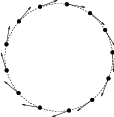
Figure 4.2: Vectors as PixelType.
The Vector class is templated over the type used to represent the spatial coordinates and over the space
dimension. Since the PixelType is independent of the PointType, we are free to select any dimension for the
vectors to be used as pixel type. However, for the sake of producing an interesting example, we will use
vectors that represent displacements of the points in the PointSet. Those vectors are then selected to be of
the same dimension as the PointSet.
Then we use the PixelType (which are actually Vectors) to instantiate the PointSet type and subsequently create a PointSet object.
The following code is generating a sphere and assigning vector values to the points. The components of the vectors in this example are computed to represent the tangents to the circle as shown in Figure 4.2.
PointSetType::PixelType tangent;
PointSetType::PointType point;
unsigned int pointId = 0;
constexpr double radius = 300.0;
for(unsigned int i=0; i<360; i++)
{
const double angle = i ⋆ itk::Math::pi / 180.0;
point[0] = radius ⋆ std::sin( angle );
point[1] = radius ⋆ std::cos( angle );
point[2] = 1.0; // flat on the Z plane
tangent[0] = std::cos(angle);
tangent[1] = -std::sin(angle);
tangent[2] = 0.0; // flat on the Z plane
pointSet->SetPoint( pointId, point );
pointSet->SetPointData( pointId, tangent );
pointId++;
}
We can now visit all the points and use the vector on the pixel values to apply a displacement on the points. This is along the spirit of what a deformable model could do at each one of its iterations.
using PointDataIterator = PointSetType::PointDataContainer::ConstIterator;
PointDataIterator pixelIterator = pointSet->GetPointData()->Begin();
PointDataIterator pixelEnd = pointSet->GetPointData()->End();
using PointIterator = PointSetType::PointsContainer::Iterator;
PointIterator pointIterator = pointSet->GetPoints()->Begin();
PointIterator pointEnd = pointSet->GetPoints()->End();
while( pixelIterator != pixelEnd && pointIterator != pointEnd )
{
pointIterator.Value() = pointIterator.Value() + pixelIterator.Value();
++pixelIterator;
++pointIterator;
}
Note that the ConstIterator was used here instead of the normal Iterator since the pixel values are only intended to be read and not modified. ITK supports const-correctness at the API level.
The itk::Vector class has overloaded the + operator with the itk::Point. In other words, vectors can be added to points in order to produce new points. This property is exploited in the center of the loop in order to update the points positions with a single statement.
We can finally visit all the points and print out the new values
Note that itk::Vector is not the appropriate class for representing normals to surfaces and gradients of functions. This is due to the way vectors behave under affine transforms. ITK has a specific class for representing normals and function gradients. This is the itk::CovariantVector class.
The source code for this section can be found in the file
PointSetWithCovariantVectors.cxx.
It is common to represent geometric objects by using points on their surfaces and normals associated with those points. This structure can be easily instantiated with the itk::PointSet class.
The natural class for representing normals to surfaces and gradients of functions is the itk::CovariantVector. A covariant vector differs from a vector in the way it behaves under affine transforms, in particular under anisotropic scaling. If a covariant vector represents the gradient of a function, the transformed covariant vector will still be the valid gradient of the transformed function, a property which would not hold with a regular vector.
The following example demonstrates how a CovariantVector can be used as the PixelType for the PointSet class. The example illustrates how a deformable model could move under the influence of the gradient of a potential function.
In order to use the CovariantVector class it is necessary to include its header file along with the header of the point set.
The CovariantVector class is templated over the type used to represent the spatial coordinates and over the space dimension. Since the PixelType is independent of the PointType, we are free to select any dimension for the covariant vectors to be used as pixel type. However, we want to illustrate here the spirit of a deformable model. It is then required for the vectors representing gradients to be of the same dimension as the points in space.
Then we use the PixelType (which are actually CovariantVectors) to instantiate the PointSet type and subsequently create a PointSet object.
The following code generates a circle and assigns gradient values to the points. The components of the CovariantVectors in this example are computed to represent the normals to the circle.
PointSetType::PixelType gradient;
PointSetType::PointType point;
unsigned int pointId = 0;
constexpr double radius = 300.0;
for(unsigned int i=0; i<360; i++)
{
const double angle = i ⋆ std::atan(1.0) / 45.0;
point[0] = radius ⋆ std::sin( angle );
point[1] = radius ⋆ std::cos( angle );
point[2] = 1.0; // flat on the Z plane
gradient[0] = std::sin(angle);
gradient[1] = std::cos(angle);
gradient[2] = 0.0; // flat on the Z plane
pointSet->SetPoint( pointId, point );
pointSet->SetPointData( pointId, gradient );
pointId++;
}
We can now visit all the points and use the vector on the pixel values to apply a deformation on the points by following the gradient of the function. This is along the spirit of what a deformable model could do at each one of its iterations. To be more formal we should use the function gradients as forces and multiply them by local stress tensors in order to obtain local deformations. The resulting deformations would finally be used to apply displacements on the points. However, to shorten the example, we will ignore this complexity for the moment.
using PointDataIterator = PointSetType::PointDataContainer::ConstIterator;
PointDataIterator pixelIterator = pointSet->GetPointData()->Begin();
PointDataIterator pixelEnd = pointSet->GetPointData()->End();
using PointIterator = PointSetType::PointsContainer::Iterator;
PointIterator pointIterator = pointSet->GetPoints()->Begin();
PointIterator pointEnd = pointSet->GetPoints()->End();
while( pixelIterator != pixelEnd && pointIterator != pointEnd )
{
point = pointIterator.Value();
gradient = pixelIterator.Value();
for(unsigned int i=0; i<Dimension; i++)
{
point[i] += gradient[i];
}
pointIterator.Value() = point;
++pixelIterator;
++pointIterator;
}
The CovariantVector class does not overload the + operator with the itk::Point. In other words, CovariantVectors can not be added to points in order to get new points. Further, since we are ignoring physics in the example, we are also forced to do the illegal addition manually between the components of the gradient and the coordinates of the points.
Note that the absence of some basic operators on the ITK geometry classes is completely intentional with the aim of preventing the incorrect use of the mathematical concepts they represent.
The source code for this section can be found in the file
Mesh1.cxx.
The itk::Mesh class is intended to represent shapes in space. It derives from the itk::PointSet class and hence inherits all the functionality related to points and access to the pixel-data associated with the points. The mesh class is also N-dimensional which allows a great flexibility in its use.
In practice a Mesh class can be seen as a PointSet to which cells (also known as elements) of many different dimensions and shapes have been added. Cells in the mesh are defined in terms of the existing points using their point-identifiers.
As with PointSet, a Mesh object may be static or dynamic. The first is used when the number of points in the set is known in advance and not expected to change as a consequence of the manipulations performed on the set. The dynamic style, on the other hand, is intended to support insertion and removal of points in an efficient manner. In addition to point management, the distinction facilitates optimization of performance and memory management of cells.
In order to use the Mesh class, its header file should be included.
Then, the type associated with the points must be selected and used for instantiating the Mesh type.
The Mesh type extensively uses the capabilities provided by Generic Programming. In particular, the Mesh class is parameterized over PixelType, spatial dimension, and (optionally) a parameter set called MeshTraits. PixelType is the type of the value associated with each point (just as is done with PointSet). The following illustrates a typical instantiation of Mesh.
Meshes typically require large amounts of memory. For this reason, they are reference counted objects, managed using itk::SmartPointers. The following line illustrates how a mesh is created by invoking the New() method on MeshType and assigning the result to a SmartPointer.
Management of points in a Mesh is identical to that in a PointSet. The type of point associated with the mesh can be obtained through the PointType trait. The following code shows the creation of points compatible with the mesh type defined above and the assignment of values to its coordinates.
MeshType::PointType p0;
MeshType::PointType p1;
MeshType::PointType p2;
MeshType::PointType p3;
p0[0]= -1.0; p0[1]= -1.0; p0[2]= 0.0; // first point ( -1, -1, 0 )
p1[0]= 1.0; p1[1]= -1.0; p1[2]= 0.0; // second point ( 1, -1, 0 )
p2[0]= 1.0; p2[1]= 1.0; p2[2]= 0.0; // third point ( 1, 1, 0 )
p3[0]= -1.0; p3[1]= 1.0; p3[2]= 0.0; // fourth point ( -1, 1, 0 )
The points can now be inserted into the Mesh using the SetPoint() method. Note that points are copied into the mesh structure, meaning that the local instances of the points can now be modified without affecting the Mesh content.
The current number of points in a mesh can be queried with the GetNumberOfPoints() method.
The points can now be efficiently accessed using the Iterator to the PointsContainer as was done in the previous section for the PointSet.
A point iterator is initialized to the first point with the Begin() method of the PointsContainer.
The ++ operator is used to advance the iterator from one point to the next. The value associated with the Point to which the iterator is pointing is obtained with the Value() method. The loop for walking through all the points is controlled by comparing the current iterator with the iterator returned by the End() method of the PointsContainer. The following illustrates the typical loop for walking through the points of a mesh.
The source code for this section can be found in the file
Mesh2.cxx.
A itk::Mesh can contain a variety of cell types. Typical cells are the itk::LineCell, itk::TriangleCell, itk::QuadrilateralCell, itk::TetrahedronCell, and itk::PolygonCell. Additional flexibility is provided for managing cells at the price of a bit more of complexity than in the case of point management.
The following code creates a polygonal line in order to illustrate the simplest case of cell management in a mesh. The only cell type used here is the LineCell. The header file of this class must be included.
For consistency with Mesh, cell types have to be configured with a number of custom types taken from the mesh traits. The set of traits relevant to cells are packaged by the Mesh class into the CellType trait. This trait needs to be passed to the actual cell types at the moment of their instantiation. The following line shows how to extract the Cell traits from the Mesh type.
The LineCell type can now be instantiated using the traits taken from the Mesh.
The main difference in the way cells and points are managed by the Mesh is that points are stored by copy on the PointsContainer while cells are stored as pointers in the CellsContainer. The reason for using pointers is that cells use C++ polymorphism on the mesh. This means that the mesh is only aware of having pointers to a generic cell which is the base class of all the specific cell types. This architecture makes it possible to combine different cell types in the same mesh. Points, on the other hand, are of a single type and have a small memory footprint, which makes it efficient to copy them directly into the container.
Managing cells by pointers adds another level of complexity to the Mesh since it is now necessary to establish a protocol to make clear who is responsible for allocating and releasing the cells’ memory. This protocol is implemented in the form of a specific type of pointer called the CellAutoPointer. This pointer, based on the itk::AutoPointer, differs in many respects from the SmartPointer. The CellAutoPointer has an internal pointer to the actual object and a boolean flag that indicates whether the CellAutoPointer is responsible for releasing the cell memory when the time comes for its own destruction. It is said that a CellAutoPointer owns the cell when it is responsible for its destruction. At any given time many CellAutoPointers can point to the same cell, but only one CellAutoPointer can own the cell.
The CellAutoPointer trait is defined in the MeshType and can be extracted as follows.
Note that the CellAutoPointer points to a generic cell type. It is not aware of the actual type of the cell, which could be (for example) a LineCell, TriangleCell or TetrahedronCell. This fact will influence the way in which we access cells later on.
At this point we can actually create a mesh and insert some points on it.
MeshType::Pointer mesh = MeshType::New();
MeshType::PointType p0;
MeshType::PointType p1;
MeshType::PointType p2;
p0[0] = -1.0; p0[1] = 0.0; p0[2] = 0.0;
p1[0] = 1.0; p1[1] = 0.0; p1[2] = 0.0;
p2[0] = 1.0; p2[1] = 1.0; p2[2] = 0.0;
mesh->SetPoint( 0, p0 );
mesh->SetPoint( 1, p1 );
mesh->SetPoint( 2, p2 );
The following code creates two CellAutoPointers and initializes them with newly created cell objects. The actual cell type created in this case is LineType. Note that cells are created with the normal new C++ operator. The CellAutoPointer takes ownership of the received pointer by using the method TakeOwnership(). Even though this may seem verbose, it is necessary in order to make it explicit that the responsibility of memory release is assumed by the AutoPointer.
The LineCells should now be associated with points in the mesh. This is done using the identifiers assigned to points when they were inserted in the mesh. Every cell type has a specific number of points that must be associated with it.4 For example, a LineCell requires two points, a TriangleCell requires three, and a TetrahedronCell requires four. Cells use an internal numbering system for points. It is simply an index in the range {0,NumberOfPoints-1}. The association of points and cells is done by the SetPointId() method, which requires the user to provide the internal index of the point in the cell and the corresponding PointIdentifier in the Mesh. The internal cell index is the first parameter of SetPointId() while the mesh point-identifier is the second.
Cells are inserted in the mesh using the SetCell() method. It requires an identifier and the AutoPointer to the cell. The Mesh will take ownership of the cell to which the CellAutoPointer is pointing. This is done internally by the SetCell() method. In this way, the destruction of the CellAutoPointer will not induce the destruction of the associated cell.
After serving as an argument of the SetCell() method, a CellAutoPointer no longer holds ownership of the cell. It is important not to use this same CellAutoPointer again as argument to SetCell() without first securing ownership of another cell.
The number of Cells currently inserted in the mesh can be queried with the GetNumberOfCells() method.
In a way analogous to points, cells can be accessed using Iterators to the CellsContainer in the mesh. The trait for the cell iterator can be extracted from the mesh and used to define a local type.
Then the iterators to the first and past-end cell in the mesh can be obtained respectively with the Begin() and End() methods of the CellsContainer. The CellsContainer of the mesh is returned by the GetCells() method.
Finally, a standard loop is used to iterate over all the cells. Note the use of the Value() method used to get the actual pointer to the cell from the CellIterator. Note also that the value returned is a pointer to the generic CellType. This pointer must be downcast in order to be used as actual LineCell types. Safe down-casting is performed with the dynamic_cast operator, which will throw an exception if the conversion cannot be safely performed.
The source code for this section can be found in the file
Mesh3.cxx.
Just as custom data can be associated with points in the mesh, it is also possible to associate custom data with cells. The type of the data associated with the cells can be different from the data type associated with points. By default, however, these two types are the same. The following example illustrates how to access data associated with cells. The approach is analogous to the one used to access point data.
Consider the example of a mesh containing lines on which values are associated with each line. The mesh and cell header files should be included first.
Then the PixelType is defined and the mesh type is instantiated with it.
The itk::LineCell type can now be instantiated using the traits taken from the Mesh.
Let’s now create a Mesh and insert some points into it. Note that the dimension of the points matches the dimension of the Mesh. Here we insert a sequence of points that look like a plot of the log() function. We add the vnl_math::eps value in order to avoid numerical errors when the point id is zero. The value of vnl_math::eps is the difference between 1.0 and the least value greater than 1.0 that is representable in this computer.
MeshType::Pointer mesh = MeshType::New();
using PointType = MeshType::PointType;
PointType point;
constexpr unsigned int numberOfPoints = 10;
for(unsigned int id=0; id<numberOfPoints; id++)
{
point[0] = static_cast<PointType::ValueType>( id ); // x
point[1] = std::log( static_cast<double>( id ) + itk::Math::eps ); // y
mesh->SetPoint( id, point );
}
A set of line cells is created and associated with the existing points by using point identifiers. In this simple case, the point identifiers can be deduced from cell identifiers since the line cells are ordered in the same way.
CellType::CellAutoPointer line;
const unsigned int numberOfCells = numberOfPoints-1;
for(unsigned int cellId=0; cellId<numberOfCells; cellId++)
{
line.TakeOwnership( new LineType );
line->SetPointId( 0, cellId ); // first point
line->SetPointId( 1, cellId+1 ); // second point
mesh->SetCell( cellId, line ); // insert the cell
}
Data associated with cells is inserted in the itk::Mesh by using the SetCellData() method. It requires the user to provide an identifier and the value to be inserted. The identifier should match one of the inserted cells. In this simple example, the square of the cell identifier is used as cell data. Note the use of static_cast to PixelType in the assignment.
Cell data can be read from the Mesh with the GetCellData() method. It requires the user to provide the identifier of the cell for which the data is to be retrieved. The user should provide also a valid pointer to a location where the data can be copied.
Neither SetCellData() or GetCellData() are efficient ways to access cell data. More efficient access to cell data can be achieved by using the Iterators built into the CellDataContainer.
Note that the ConstIterator is used here because the data is only going to be read. This approach is exactly the same already illustrated for getting access to point data. The iterator to the first cell data item can be obtained with the Begin() method of the CellDataContainer. The past-end iterator is returned by the End() method. The cell data container itself can be obtained from the mesh with the method GetCellData().
Finally, a standard loop is used to iterate over all the cell data entries. Note the use of the Value() method to get the value associated with the data entry. PixelType elements are copied into the local variable cellValue.
The source code for this section can be found in the file
MeshTraits.cxx.
This section illustrates the full power of Generic Programming. This is sometimes perceived as too much of a good thing!
The toolkit has been designed to offer flexibility while keeping the complexity of the code to a moderate level. This is achieved in the Mesh by hiding most of its parameters and defining reasonable defaults for them.
The generic concept of a mesh integrates many different elements. It is possible in principle to use independent types for every one of such elements. The mechanism used in generic programming for specifying the many different types involved in a concept is called traits. They are basically the list of all types that interact with the current class.
The itk::Mesh is templated over three parameters. So far only two of them have been discussed, namely the PixelType and the Dimension. The third parameter is a class providing the set of traits required by the mesh. When the third parameter is omitted a default class is used. This default class is the itk::DefaultStaticMeshTraits. If you want to customize the types used by the mesh, the way to proceed is to modify the default traits and provide them as the third parameter of the Mesh class instantiation.
There are two ways of achieving this. The first is to use the existing itk::DefaultStaticMeshTraits class. This class is itself templated over six parameters. Customizing those parameters could provide enough flexibility to define a very specific kind of mesh. The second way is to write a traits class from scratch, in which case the easiest way to proceed is to copy the DefaultStaticMeshTraits into another file and edit its content. Only the first approach is illustrated here. The second is discouraged unless you are familiar with Generic Programming, feel comfortable with C++ templates, and have access to an abundant supply of (Columbian) coffee.
The first step in customizing the mesh is to include the header file of the Mesh and its static traits.
Then the MeshTraits class is instantiated by selecting the types of each one of its six template arguments. They are in order
Let’s define types and values for each one of those elements. For example, the following code uses points in 3D space as nodes of the Mesh. The maximum dimension of the cells will be two, meaning that this is a 2D manifold better know as a surface. The data type associated with points is defined to be a four-dimensional vector. This type could represent values of membership for a four-class segmentation method. The value selected for the cells are 4×3 matrices, which could have for example the derivative of the membership values with respect to coordinates in space. Finally, a double type is selected for representing space coordinates on the mesh points and also for the weight used for interpolating values.
constexpr unsigned int PointDimension = 3;
constexpr unsigned int MaxTopologicalDimension = 2;
using PixelType = itk::Vector<double,4>;
using CellDataType = itk::Matrix<double,4,3>;
using CoordinateType = double;
using InterpolationWeightType = double;
using MeshTraits = itk::DefaultStaticMeshTraits<
PixelType, PointDimension, MaxTopologicalDimension,
CoordinateType, InterpolationWeightType, CellDataType >;
using MeshType = itk::Mesh< PixelType, PointDimension, MeshTraits >;
The itk::LineCell type can now be instantiated using the traits taken from the Mesh.
Let’s now create an Mesh and insert some points on it. Note that the dimension of the points matches the dimension of the Mesh. Here we insert a sequence of points that look like a plot of the log() function.
MeshType::Pointer mesh = MeshType::New();
using PointType = MeshType::PointType;
PointType point;
constexpr unsigned int numberOfPoints = 10;
for(unsigned int id=0; id<numberOfPoints; id++)
{
point[0] = 1.565; // Initialize points here
point[1] = 3.647; // with arbitrary values
point[2] = 4.129;
mesh->SetPoint( id, point );
}
A set of line cells is created and associated with the existing points by using point identifiers. In this simple case, the point identifiers can be deduced from cell identifiers since the line cells are ordered in the same way. Note that in the code above, the values assigned to point components are arbitrary. In a more realistic example, those values would be computed from another source.
CellType::CellAutoPointer line;
const unsigned int numberOfCells = numberOfPoints-1;
for(unsigned int cellId=0; cellId<numberOfCells; cellId++)
{
line.TakeOwnership( new LineType );
line->SetPointId( 0, cellId ); // first point
line->SetPointId( 1, cellId+1 ); // second point
mesh->SetCell( cellId, line ); // insert the cell
}
Data associated with cells is inserted in the Mesh by using the SetCellData() method. It requires the user to provide an identifier and the value to be inserted. The identifier should match one of the inserted cells. In this example, we simply store a CellDataType dummy variable named value.
Cell data can be read from the Mesh with the GetCellData() method. It requires the user to provide the identifier of the cell for which the data is to be retrieved. The user should provide also a valid pointer to a location where the data can be copied.
Neither SetCellData() or GetCellData() are efficient ways to access cell data. Efficient access to cell data can be achieved by using the Iterators built into the CellDataContainer.
Note that the ConstIterator is used here because the data is only going to be read. This approach is identical to that already illustrated for accessing point data. The iterator to the first cell data item can be obtained with the Begin() method of the CellDataContainer. The past-end iterator is returned by the End() method. The cell data container itself can be obtained from the mesh with the method GetCellData().
Finally a standard loop is used to iterate over all the cell data entries. Note the use of the Value() method used to get the actual value of the data entry. PixelType elements are returned by copy.
The source code for this section can be found in the file
MeshKComplex.cxx.
The itk::Mesh class supports the representation of formal topologies. In particular the concept of K-Complex can be correctly represented in the Mesh. An informal definition of K-Complex may be as follows: a K-Complex is a topological structure in which for every cell of dimension N, its boundary faces (which are cells of dimension N -1) also belong to the structure.
This section illustrates how to instantiate a K-Complex structure using the mesh. The example structure is composed of one tetrahedron, its four triangle faces, its six line edges and its four vertices.
The header files of all the cell types involved should be loaded along with the header file of the mesh class.
Then the PixelType is defined and the mesh type is instantiated with it. Note that the dimension of the space is three in this case.
The cell type can now be instantiated using the traits taken from the Mesh.
The mesh is created and the points associated with the vertices are inserted. Note that there is an important distinction between the points in the mesh and the itk::VertexCell concept. A VertexCell is a cell of dimension zero. Its main difference as compared to a point is that the cell can be aware of neighborhood relationships with other cells. Points are not aware of the existence of cells. In fact, from the pure topological point of view, the coordinates of points in the mesh are completely irrelevant. They may as well be absent from the mesh structure altogether. VertexCells on the other hand are necessary to represent the full set of neighborhood relationships on the K-Complex.
The geometrical coordinates of the nodes of a regular tetrahedron can be obtained by taking every other node from a regular cube.
MeshType::Pointer mesh = MeshType::New();
MeshType::PointType point0;
MeshType::PointType point1;
MeshType::PointType point2;
MeshType::PointType point3;
point0[0] = -1; point0[1] = -1; point0[2] = -1;
point1[0] = 1; point1[1] = 1; point1[2] = -1;
point2[0] = 1; point2[1] = -1; point2[2] = 1;
point3[0] = -1; point3[1] = 1; point3[2] = 1;
mesh->SetPoint( 0, point0 );
mesh->SetPoint( 1, point1 );
mesh->SetPoint( 2, point2 );
mesh->SetPoint( 3, point3 );
We proceed now to create the cells, associate them with the points and insert them on the mesh. Starting with the tetrahedron we write the following code.
Four triangular faces are created and associated with the mesh now. The first triangle connects points 0,1,2.
The second triangle connects points 0, 2, 3 .
The third triangle connects points 0, 3, 1 .
The fourth triangle connects points 3, 2, 1 .
Note how the CellAutoPointer is reused every time. Reminder: the itk::AutoPointer loses ownership of the cell when it is passed as an argument of the SetCell() method. The AutoPointer is attached to a new cell by using the TakeOwnership() method.
The construction of the K-Complex continues now with the creation of the six lines on the tetrahedron edges.
cellpointer.TakeOwnership( new LineType );
cellpointer->SetPointId( 0, 0 );
cellpointer->SetPointId( 1, 1 );
mesh->SetCell( 5, cellpointer );
cellpointer.TakeOwnership( new LineType );
cellpointer->SetPointId( 0, 1 );
cellpointer->SetPointId( 1, 2 );
mesh->SetCell( 6, cellpointer );
cellpointer.TakeOwnership( new LineType );
cellpointer->SetPointId( 0, 2 );
cellpointer->SetPointId( 1, 0 );
mesh->SetCell( 7, cellpointer );
cellpointer.TakeOwnership( new LineType );
cellpointer->SetPointId( 0, 1 );
cellpointer->SetPointId( 1, 3 );
mesh->SetCell( 8, cellpointer );
cellpointer.TakeOwnership( new LineType );
cellpointer->SetPointId( 0, 3 );
cellpointer->SetPointId( 1, 2 );
mesh->SetCell( 9, cellpointer );
cellpointer.TakeOwnership( new LineType );
cellpointer->SetPointId( 0, 3 );
cellpointer->SetPointId( 1, 0 );
mesh->SetCell( 10, cellpointer );
Finally the zero dimensional cells represented by the itk::VertexCell are created and inserted in the mesh.
cellpointer.TakeOwnership( new VertexType );
cellpointer->SetPointId( 0, 0 );
mesh->SetCell( 11, cellpointer );
cellpointer.TakeOwnership( new VertexType );
cellpointer->SetPointId( 0, 1 );
mesh->SetCell( 12, cellpointer );
cellpointer.TakeOwnership( new VertexType );
cellpointer->SetPointId( 0, 2 );
mesh->SetCell( 13, cellpointer );
cellpointer.TakeOwnership( new VertexType );
cellpointer->SetPointId( 0, 3 );
mesh->SetCell( 14, cellpointer );
At this point the Mesh contains four points and fifteen cells enumerated from 0 to 14. The points can be visited using PointContainer iterators.
The cells can be visited using CellsContainer iterators.
using CellIterator = MeshType::CellsContainer::ConstIterator;
CellIterator cellIterator = mesh->GetCells()->Begin();
CellIterator cellEnd = mesh->GetCells()->End();
while( cellIterator != cellEnd )
{
CellType ⋆ cell = cellIterator.Value();
std::cout << cell->GetNumberOfPoints() << std::endl;
++cellIterator;
}
Note that cells are stored as pointer to a generic cell type that is the base class of all the specific cell classes. This means that at this level we can only have access to the virtual methods defined in the CellType.
The point identifiers to which the cells have been associated can be visited using iterators defined in the CellType trait. The following code illustrates the use of the PointIdIterators. The PointIdsBegin() method returns the iterator to the first point-identifier in the cell. The PointIdsEnd() method returns the iterator to the past-end point-identifier in the cell.
Note that the point-identifier is obtained from the iterator using the more traditional ⋆iterator notation instead the Value() notation used by cell-iterators.
Up to here, the topology of the K-Complex is not completely defined since we have only introduced the cells. ITK allows the user to define explicitly the neighborhood relationships between cells. It is clear that a clever exploration of the point identifiers could have allowed a user to figure out the neighborhood relationships. For example, two triangle cells sharing the same two point identifiers will probably be neighbor cells. Some of the drawbacks on this implicit discovery of neighborhood relationships is that it takes computing time and that some applications may not accept the same assumptions. A specific case is surgery simulation. This application typically simulates bistoury cuts in a mesh representing an organ. A small cut in the surface may be made by specifying that two triangles are not considered to be neighbors any more.
Neighborhood relationships are represented in the mesh by the notion of BoundaryFeature. Every cell has an internal list of cell-identifiers pointing to other cells that are considered to be its neighbors. Boundary features are classified by dimension. For example, a line will have two boundary features of dimension zero corresponding to its two vertices. A tetrahedron will have boundary features of dimension zero, one and two, corresponding to its four vertices, six edges and four triangular faces. It is up to the user to specify the connections between the cells.
Let’s take in our current example the tetrahedron cell that was associated with the cell-identifier 0 and assign to it the four vertices as boundaries of dimension zero. This is done by invoking the SetBoundaryAssignment() method on the Mesh class.
MeshType::CellIdentifier cellId = 0; // the tetrahedron
int dimension = 0; // vertices
MeshType::CellFeatureIdentifier featureId = 0;
mesh->SetBoundaryAssignment( dimension, cellId, featureId++, 11 );
mesh->SetBoundaryAssignment( dimension, cellId, featureId++, 12 );
mesh->SetBoundaryAssignment( dimension, cellId, featureId++, 13 );
mesh->SetBoundaryAssignment( dimension, cellId, featureId++, 14 );
The featureId is simply a number associated with the sequence of the boundary cells of the same dimension in a specific cell. For example, the zero-dimensional features of a tetrahedron are its four vertices. Then the zero-dimensional feature-Ids for this cell will range from zero to three. The one-dimensional features of the tetrahedron are its six edges, hence its one-dimensional feature-Ids will range from zero to five. The two-dimensional features of the tetrahedron are its four triangular faces. The two-dimensional feature ids will then range from zero to three. The following table summarizes the use on indices for boundary assignments.
| Dimension | CellType | FeatureId range | Cell Ids |
| 0 | VertexCell | [0:3] | {11,12,13,14} |
| 1 | LineCell | [0:5] | {5,6,7,8,9,10} |
| 2 | TriangleCell | [0:3] | {1,2,3,4} |
In the code example above, the values of featureId range from zero to three. The cell identifiers of the triangle cells in this example are the numbers {1,2,3,4}, while the cell identifiers of the vertex cells are the numbers {11,12,13,14}.
Let’s now assign one-dimensional boundary features of the tetrahedron. Those are the line cells with identifiers {5,6,7,8,9,10}. Note that the feature identifier is reinitialized to zero since the count is independent for each dimension.
cellId = 0; // still the tetrahedron
dimension = 1; // one-dimensional features = edges
featureId = 0; // reinitialize the count
mesh->SetBoundaryAssignment( dimension, cellId, featureId++, 5 );
mesh->SetBoundaryAssignment( dimension, cellId, featureId++, 6 );
mesh->SetBoundaryAssignment( dimension, cellId, featureId++, 7 );
mesh->SetBoundaryAssignment( dimension, cellId, featureId++, 8 );
mesh->SetBoundaryAssignment( dimension, cellId, featureId++, 9 );
mesh->SetBoundaryAssignment( dimension, cellId, featureId++, 10 );
Finally we assign the two-dimensional boundary features of the tetrahedron. These are the four triangular cells with identifiers {1,2,3,4}. The featureId is reset to zero since feature-Ids are independent on each dimension.
cellId = 0; // still the tetrahedron
dimension = 2; // two-dimensional features = triangles
featureId = 0; // reinitialize the count
mesh->SetBoundaryAssignment( dimension, cellId, featureId++, 1 );
mesh->SetBoundaryAssignment( dimension, cellId, featureId++, 2 );
mesh->SetBoundaryAssignment( dimension, cellId, featureId++, 3 );
mesh->SetBoundaryAssignment( dimension, cellId, featureId++, 4 );
At this point we can query the tetrahedron cell for information about its boundary features. For example, the number of boundary features of each dimension can be obtained with the method GetNumberOfBoundaryFeatures().
cellId = 0; // still the tetrahedron
MeshType::CellFeatureCount n0; // number of zero-dimensional features
MeshType::CellFeatureCount n1; // number of one-dimensional features
MeshType::CellFeatureCount n2; // number of two-dimensional features
n0 = mesh->GetNumberOfCellBoundaryFeatures( 0, cellId );
n1 = mesh->GetNumberOfCellBoundaryFeatures( 1, cellId );
n2 = mesh->GetNumberOfCellBoundaryFeatures( 2, cellId );
The boundary assignments can be recovered with the method GetBoundaryAssigment(). For example, the zero-dimensional features of the tetrahedron can be obtained with the following code.
The following code illustrates how to set the edge boundaries for one of the triangular faces.
cellId = 2; // one of the triangles
dimension = 1; // boundary edges
featureId = 0; // start the count of features
mesh->SetBoundaryAssignment( dimension, cellId, featureId++, 7 );
mesh->SetBoundaryAssignment( dimension, cellId, featureId++, 9 );
mesh->SetBoundaryAssignment( dimension, cellId, featureId++, 10 );
The source code for this section can be found in the file
MeshPolyLine.cxx.
This section illustrates how to represent a classical PolyLine structure using the itk::Mesh
A PolyLine only involves zero and one dimensional cells, which are represented by the itk::VertexCell and the itk::LineCell.
Then the PixelType is defined and the mesh type is instantiated with it. Note that the dimension of the space is two in this case.
The cell type can now be instantiated using the traits taken from the Mesh.
The mesh is created and the points associated with the vertices are inserted. Note that there is an important distinction between the points in the mesh and the itk::VertexCell concept. A VertexCell is a cell of dimension zero. Its main difference as compared to a point is that the cell can be aware of neighborhood relationships with other cells. Points are not aware of the existence of cells. In fact, from the pure topological point of view, the coordinates of points in the mesh are completely irrelevant. They may as well be absent from the mesh structure altogether. VertexCells on the other hand are necessary to represent the full set of neighborhood relationships on the Polyline.
In this example we create a polyline connecting the four vertices of a square by using three of the square sides.
MeshType::Pointer mesh = MeshType::New();
MeshType::PointType point0;
MeshType::PointType point1;
MeshType::PointType point2;
MeshType::PointType point3;
point0[0] = -1; point0[1] = -1;
point1[0] = 1; point1[1] = -1;
point2[0] = 1; point2[1] = 1;
point3[0] = -1; point3[1] = 1;
mesh->SetPoint( 0, point0 );
mesh->SetPoint( 1, point1 );
mesh->SetPoint( 2, point2 );
mesh->SetPoint( 3, point3 );
We proceed now to create the cells, associate them with the points and insert them on the mesh.
CellType::CellAutoPointer cellpointer;
cellpointer.TakeOwnership( new LineType );
cellpointer->SetPointId( 0, 0 );
cellpointer->SetPointId( 1, 1 );
mesh->SetCell( 0, cellpointer );
cellpointer.TakeOwnership( new LineType );
cellpointer->SetPointId( 0, 1 );
cellpointer->SetPointId( 1, 2 );
mesh->SetCell( 1, cellpointer );
cellpointer.TakeOwnership( new LineType );
cellpointer->SetPointId( 0, 2 );
cellpointer->SetPointId( 1, 0 );
mesh->SetCell( 2, cellpointer );
Finally the zero dimensional cells represented by the itk::VertexCell are created and inserted in the mesh.
cellpointer.TakeOwnership( new VertexType );
cellpointer->SetPointId( 0, 0 );
mesh->SetCell( 3, cellpointer );
cellpointer.TakeOwnership( new VertexType );
cellpointer->SetPointId( 0, 1 );
mesh->SetCell( 4, cellpointer );
cellpointer.TakeOwnership( new VertexType );
cellpointer->SetPointId( 0, 2 );
mesh->SetCell( 5, cellpointer );
cellpointer.TakeOwnership( new VertexType );
cellpointer->SetPointId( 0, 3 );
mesh->SetCell( 6, cellpointer );
At this point the Mesh contains four points and three cells. The points can be visited using PointContainer iterators.
The cells can be visited using CellsContainer iterators.
using CellIterator = MeshType::CellsContainer::ConstIterator;
CellIterator cellIterator = mesh->GetCells()->Begin();
CellIterator cellEnd = mesh->GetCells()->End();
while( cellIterator != cellEnd )
{
CellType ⋆ cell = cellIterator.Value();
std::cout << cell->GetNumberOfPoints() << std::endl;
++cellIterator;
}
Note that cells are stored as pointer to a generic cell type that is the base class of all the specific cell classes. This means that at this level we can only have access to the virtual methods defined in the CellType.
The point identifiers to which the cells have been associated can be visited using iterators defined in the CellType trait. The following code illustrates the use of the PointIdIterator. The PointIdsBegin() method returns the iterator to the first point-identifier in the cell. The PointIdsEnd() method returns the iterator to the past-end point-identifier in the cell.
Note that the point-identifier is obtained from the iterator using the more traditional ⋆iterator notation instead the Value() notation used by cell-iterators.
The source code for this section can be found in the file
AutomaticMesh.cxx.
The itk::Mesh class is extremely general and flexible, but there is some cost to convenience. If convenience is exactly what you need, then it is possible to get it, in exchange for some of that flexibility, by means of the itk::AutomaticTopologyMeshSource class. This class automatically generates an explicit K-Complex, based on the cells you add. It explicitly includes all boundary information, so that the resulting mesh can be easily traversed. It merges all shared edges, vertices, and faces, so no geometric feature appears more than once.
This section shows how you can use the AutomaticTopologyMeshSource to instantiate a mesh representing a K-Complex. We will first generate the same tetrahedron from Section 4.3.5, after which we will add a hollow one to illustrate some additional features of the mesh source.
The header files of all the cell types involved should be loaded along with the header file of the mesh class.
We then define the necessary types and instantiate the mesh source. Two new types are IdentifierType and IdentifierArrayType. Every cell in a mesh has an identifier, whose type is determined by the mesh traits. AutomaticTopologyMeshSource requires that the identifier type of all vertices and cells be unsigned long, which is already the default. However, if you created a new mesh traits class to use string tags as identifiers, the resulting mesh would not be compatible with itk::AutomaticTopologyMeshSource. An IdentifierArrayType is simply an itk::Array of IdentifierType objects.
using PixelType = float;
using MeshType = itk::Mesh< PixelType, 3 >;
using PointType = MeshType::PointType;
using MeshSourceType = itk::AutomaticTopologyMeshSource< MeshType >;
using IdentifierArrayType = MeshSourceType::IdentifierArrayType;
MeshSourceType::Pointer meshSource;
meshSource = MeshSourceType::New();
Now let us generate the tetrahedron. The following line of code generates all the vertices, edges, and faces, along with the tetrahedral solid, and adds them to the mesh along with the connectivity information.
The function AutomaticTopologyMeshSource::AddTetrahedron() takes point identifiers as parameters; the identifiers must correspond to points that have already been added. AutomaticTopologyMeshSource::AddPoint() returns the appropriate identifier type for the point being added. It first checks to see if the point is already in the mesh. If so, it returns the ID of the point in the mesh, and if not, it generates a new unique ID, adds the point with that ID, and returns the ID.
Actually, AddTetrahedron() behaves in the same way. If the tetrahedron has already been added, it leaves the mesh unchanged and returns the ID that the tetrahedron already has. If not, it adds the tetrahedron (and all its faces, edges, and vertices), and generates a new ID, which it returns.
It is also possible to add all the points first, and then add a number of cells using the point IDs directly. This approach corresponds with the way the data is stored in many file formats for 3D polygonal models.
First we add the points (in this case the vertices of a larger tetrahedron). This example also illustrates that AddPoint() can take a single PointType as a parameter if desired, rather than a sequence of floats. Another possibility (not illustrated) is to pass in a C-style array.
PointType p;
IdentifierArrayType idArray( 4 );
p[ 0 ] = -2;
p[ 1 ] = -2;
p[ 2 ] = -2;
idArray[ 0 ] = meshSource->AddPoint( p );
p[ 0 ] = 2;
p[ 1 ] = 2;
p[ 2 ] = -2;
idArray[ 1 ] = meshSource->AddPoint( p );
p[ 0 ] = 2;
p[ 1 ] = -2;
p[ 2 ] = 2;
idArray[ 2 ] = meshSource->AddPoint( p );
p[ 0 ] = -2;
p[ 1 ] = 2;
p[ 2 ] = 2;
idArray[ 3 ] = meshSource->AddPoint( p );
Now we add the cells. This time we are just going to create the boundary of a tetrahedron, so we must add each face separately.
Actually, we could have called, e.g., AddTriangle( 4, 5, 6 ), since IDs are assigned sequentially starting at zero, and idArray[0] contains the ID for the fifth point added. But you should only do this if you are confident that you know what the IDs are. If you add the same point twice and don’t realize it, your count will differ from that of the mesh source.
You may be wondering what happens if you call, say, AddEdge(0, 1) followed by AddEdge(1, 0). The answer is that they do count as the same edge, and so only one edge is added. The order of the vertices determines an orientation, and the first orientation specified is the one that is kept.
Once you have built the mesh you want, you can access it by calling GetOutput(). Here we send it to cout, which prints some summary data for the mesh.
In contrast to the case with typical filters, GetOutput() does not trigger an update process. The mesh is always maintained in a valid state as cells are added, and can be accessed at any time. It would, however, be a mistake to modify the mesh by some other means until AutomaticTopologyMeshSource is done with it, since the mesh source would then have an inaccurate record of which points and cells are currently in the mesh.
The source code for this section can be found in the file
MeshCellsIteration.cxx.
Cells are stored in the itk::Mesh as pointers to a generic cell itk::CellInterface. This implies that only the virtual methods defined on this base cell class can be invoked. In order to use methods that are specific to each cell type it is necessary to down-cast the pointer to the actual type of the cell. This can be done safely by taking advantage of the GetType() method that allows to identify the actual type of a cell.
Let’s start by assuming a mesh defined with one tetrahedron and all its boundary faces. That is, four triangles, six edges and four vertices.
The cells can be visited using CellsContainer iterators . The iterator Value() corresponds to a raw pointer to the CellType base class.
using CellIterator = MeshType::CellsContainer::ConstIterator;
CellIterator cellIterator = mesh->GetCells()->Begin();
CellIterator cellEnd = mesh->GetCells()->End();
while( cellIterator != cellEnd )
{
CellType ⋆ cell = cellIterator.Value();
std::cout << cell->GetNumberOfPoints() << std::endl;
++cellIterator;
}
In order to perform down-casting in a safe manner, the cell type can be queried first using the GetType() method. Codes for the cell types have been defined with an enum type on the itkCellInterface.h header file. These codes are :
The method GetType() returns one of these codes. It is then possible to test the type of the cell before down-casting its pointer to the actual type. For example, the following code visits all the cells in the mesh and tests which ones are actually of type LINE_CELL. Only those cells are down-casted to LineType cells and a method specific for the LineType is invoked.
cellIterator = mesh->GetCells()->Begin();
cellEnd = mesh->GetCells()->End();
while( cellIterator != cellEnd )
{
CellType ⋆ cell = cellIterator.Value();
if( cell->GetType() == CellType::LINE_CELL )
{
auto ⋆ line = static_cast<LineType ⋆>( cell );
std::cout << "dimension = " << line->GetDimension();
std::cout << " # points = " << line->GetNumberOfPoints();
std::cout << std::endl;
}
++cellIterator;
}
In order to perform different actions on different cell types a switch statement can be used with cases for every cell type. The following code illustrates an iteration over the cells and the invocation of different methods on each cell type.
cellIterator = mesh->GetCells()->Begin();
cellEnd = mesh->GetCells()->End();
while( cellIterator != cellEnd )
{
CellType ⋆ cell = cellIterator.Value();
switch( cell->GetType() )
{
case CellType::VERTEX_CELL:
{
std::cout << "VertexCell : " << std::endl;
auto ⋆ line = dynamic_cast<VertexType ⋆>( cell );
std::cout << "dimension = " << line->GetDimension() << std::endl;
std::cout << "# points = " << line->GetNumberOfPoints() << std::endl;
break;
}
case CellType::LINE_CELL:
{
std::cout << "LineCell : " << std::endl;
auto ⋆ line = dynamic_cast<LineType ⋆>( cell );
std::cout << "dimension = " << line->GetDimension() << std::endl;
std::cout << "# points = " << line->GetNumberOfPoints() << std::endl;
break;
}
case CellType::TRIANGLE_CELL:
{
std::cout << "TriangleCell : " << std::endl;
auto ⋆ line = dynamic_cast<TriangleType ⋆>( cell );
std::cout << "dimension = " << line->GetDimension() << std::endl;
std::cout << "# points = " << line->GetNumberOfPoints() << std::endl;
break;
}
default:
{
std::cout << "Cell with more than three points" << std::endl;
std::cout << "dimension = " << cell->GetDimension() << std::endl;
std::cout << "# points = " << cell->GetNumberOfPoints() << std::endl;
break;
}
}
++cellIterator;
}
The source code for this section can be found in the file
MeshCellVisitor.cxx.
In order to facilitate access to particular cell types, a convenience mechanism has been built-in on the itk::Mesh. This mechanism is based on the Visitor Pattern presented in [?]. The visitor pattern is designed to facilitate the process of walking through an heterogeneous list of objects sharing a common base class.
The first requirement for using the CellVisitor mechanism it to include the CellInterfaceVisitor header file.
The typical mesh types are now declared.
using PixelType = float;
using MeshType = itk::Mesh< PixelType, 3 >;
using CellType = MeshType::CellType;
using VertexType = itk::VertexCell< CellType >;
using LineType = itk::LineCell< CellType >;
using TriangleType = itk::TriangleCell< CellType >;
using TetrahedronType = itk::TetrahedronCell< CellType >;
Then, a custom CellVisitor class should be declared. In this particular example, the visitor class is intended to act only on TriangleType cells. The only requirement on the declaration of the visitor class is that it must provide a method named Visit(). This method expects as arguments a cell identifier and a pointer to the specific cell type for which this visitor is intended. Nothing prevents a visitor class from providing Visit() methods for several different cell types. The multiple methods will be differentiated by the natural C++ mechanism of function overload. The following code illustrates a minimal cell visitor class.
class CustomTriangleVisitor
{
public:
using TriangleType = itk::TriangleCell<CellType>;
void Visit(unsigned long cellId, TriangleType ⋆ t )
{
std::cout << "Cell # " << cellId << " is a TriangleType ";
std::cout << t->GetNumberOfPoints() << std::endl;
}
CustomTriangleVisitor() = default;
virtual ~CustomTriangleVisitor() = default;
};
This newly defined class will now be used to instantiate a cell visitor. In this particular example we create a class CustomTriangleVisitor which will be invoked each time a triangle cell is found while the mesh iterates over the cells.
Note that the actual CellInterfaceVisitorImplementation is templated over the PixelType, the CellTraits, the CellType to be visited and the Visitor class that defines with will be done with the cell.
A visitor implementation class can now be created using the normal invocation to its New() method and assigning the result to a itk::SmartPointer.
Many different visitors can be configured in this way. The set of all visitors can be registered with the MultiVisitor class provided for the mesh. An instance of the MultiVisitor class will walk through the cells and delegate action to every registered visitor when the appropriate cell type is encountered.
The visitor is registered with the Mesh using the AddVisitor() method.
Finally, the iteration over the cells is triggered by calling the method Accept() on the itk::Mesh.
The Accept() method will iterate over all the cells and for each one will invite the MultiVisitor to attempt an action on the cell. If no visitor is interested on the current cell type the cell is just ignored and skipped.
MultiVisitors make it possible to add behavior to the cells without having to create new methods on the cell types or creating a complex visitor class that knows about every CellType.
The source code for this section can be found in the file
MeshCellVisitor2.cxx.
The following section illustrates a realistic example of the use of Cell visitors on the itk::Mesh. A set of different visitors is defined here, each visitor associated with a particular type of cell. All the visitors are registered with a MultiVisitor class which is passed to the mesh.
The first step is to include the CellInterfaceVisitor header file.
The typical mesh types are now declared.
using PixelType = float;
using MeshType = itk::Mesh< PixelType, 3 >;
using CellType = MeshType::CellType;
using VertexType = itk::VertexCell< CellType >;
using LineType = itk::LineCell< CellType >;
using TriangleType = itk::TriangleCell< CellType >;
using TetrahedronType = itk::TetrahedronCell< CellType >;
Then, custom CellVisitor classes should be declared. The only requirement on the declaration of each visitor class is to provide a method named Visit(). This method expects as arguments a cell identifier and a pointer to the specific cell type for which this visitor is intended.
The following Vertex visitor simply prints out the identifier of the point with which the cell is associated. Note that the cell uses the method GetPointId() without any arguments. This method is only defined on the VertexCell.
The following Line visitor computes the length of the line. Note that this visitor is slightly more complicated since it needs to get access to the actual mesh in order to get point coordinates from the point identifiers returned by the line cell. This is done by holding a pointer to the mesh and querying the mesh each time point coordinates are required. The mesh pointer is set up in this case with the SetMesh() method.
class CustomLineVisitor
{
public:
CustomLineVisitor():m_Mesh( nullptr ) {}
virtual ~CustomLineVisitor() = default;
void SetMesh( MeshType ⋆ mesh ) { m_Mesh = mesh; }
void Visit(unsigned long cellId, LineType ⋆ t )
{
std::cout << "cell " << cellId << " is a Line " << std::endl;
LineType::PointIdIterator pit = t->PointIdsBegin();
MeshType::PointType p0;
MeshType::PointType p1;
m_Mesh->GetPoint( ⋆pit++, &p0 );
m_Mesh->GetPoint( ⋆pit++, &p1 );
const double length = p0.EuclideanDistanceTo( p1 );
std::cout << " length = " << length << std::endl;
}
private:
MeshType::Pointer m_Mesh;
};
The Triangle visitor below prints out the identifiers of its points. Note the use of the PointIdIterator and the PointIdsBegin() and PointIdsEnd() methods.
class CustomTriangleVisitor
{
public:
void Visit(unsigned long cellId, TriangleType ⋆ t )
{
std::cout << "cell " << cellId << " is a Triangle " << std::endl;
LineType::PointIdIterator pit = t->PointIdsBegin();
LineType::PointIdIterator end = t->PointIdsEnd();
while( pit != end )
{
std::cout << " point id = " << ⋆pit << std::endl;
++pit;
}
}
virtual ~CustomTriangleVisitor() = default;
};
The TetrahedronVisitor below simply returns the number of faces on this figure. Note that GetNumberOfFaces() is a method exclusive of 3D cells.
class CustomTetrahedronVisitor
{
public:
void Visit(unsigned long cellId, TetrahedronType ⋆ t )
{
std::cout << "cell " << cellId << " is a Tetrahedron " << std::endl;
std::cout << " number of faces = ";
std::cout << t->GetNumberOfFaces() << std::endl;
}
virtual ~CustomTetrahedronVisitor() = default;
};
With the cell visitors we proceed now to instantiate CellVisitor implementations. The visitor classes defined above are used as template arguments of the cell visitor implementation.
using VertexVisitorInterfaceType = itk::CellInterfaceVisitorImplementation<
PixelType, MeshType::CellTraits, VertexType,
CustomVertexVisitor >;
using LineVisitorInterfaceType = itk::CellInterfaceVisitorImplementation<
PixelType, MeshType::CellTraits, LineType,
CustomLineVisitor >;
using TriangleVisitorInterfaceType = itk::CellInterfaceVisitorImplementation<
PixelType, MeshType::CellTraits, TriangleType,
CustomTriangleVisitor >;
using TetrahedronVisitorInterfaceType =
itk::CellInterfaceVisitorImplementation<
PixelType, MeshType::CellTraits, TetrahedronType,
CustomTetrahedronVisitor >;
Note that the actual CellInterfaceVisitorImplementation is templated over the PixelType, the CellTraits, the CellType to be visited and the Visitor class defining what to do with the cell.
A visitor implementation class can now be created using the normal invocation to its New() method and assigning the result to a itk::SmartPointer.
VertexVisitorInterfaceType::Pointer vertexVisitor =
VertexVisitorInterfaceType::New();
LineVisitorInterfaceType::Pointer lineVisitor =
LineVisitorInterfaceType::New();
TriangleVisitorInterfaceType::Pointer triangleVisitor =
TriangleVisitorInterfaceType::New();
TetrahedronVisitorInterfaceType::Pointer tetrahedronVisitor =
TetrahedronVisitorInterfaceType::New();
Remember that the LineVisitor requires the pointer to the mesh object since it needs to get access to actual point coordinates. This is done by invoking the SetMesh() method defined above.
Looking carefully you will notice that the SetMesh() method is declared in CustomLineVisitor but we are invoking it on LineVisitorInterfaceType. This is possible thanks to the way in which the VisitorInterfaceImplementation is defined. This class derives from the visitor type provided by the user as the fourth template parameter. LineVisitorInterfaceType is then a derived class of CustomLineVisitor.
The set of visitors should now be registered with the MultiVisitor class that will walk through the cells and delegate action to every registered visitor when the appropriate cell type is encountered. The following lines create a MultiVisitor object.
Every visitor implementation is registered with the Mesh using the AddVisitor() method.
Finally, the iteration over the cells is triggered by calling the method Accept() on the Mesh class.
The Accept() method will iterate over all the cells and for each one will invite the MultiVisitor to attempt an action on the cell. If no visitor is interested on the current cell type, the cell is just ignored and skipped.
The source code for this section can be found in the file
PolyLineParametricPath1.cxx.
This example illustrates how to use the itk::PolyLineParametricPath. This class will typically be used for representing in a concise way the output of an image segmentation algorithm in 2D. The PolyLineParametricPath however could also be used for representing any open or close curve in N-Dimensions as a linear piece-wise approximation.
First, the header file of the PolyLineParametricPath class must be included.
The path is instantiated over the dimension of the image. In this example the image and path are
two-dimensional.
ImageType::ConstPointer image = reader->GetOutput();
PathType::Pointer path = PathType::New();
path->Initialize();
using ContinuousIndexType = PathType::ContinuousIndexType;
ContinuousIndexType cindex;
using ImagePointType = ImageType::PointType;
ImagePointType origin = image->GetOrigin();
ImageType::SpacingType spacing = image->GetSpacing();
ImageType::SizeType size = image->GetBufferedRegion().GetSize();
ImagePointType point;
point[0] = origin[0] + spacing[0] ⋆ size[0];
point[1] = origin[1] + spacing[1] ⋆ size[1];
image->TransformPhysicalPointToContinuousIndex( origin, cindex );
path->AddVertex( cindex );
image->TransformPhysicalPointToContinuousIndex( point, cindex );
path->AddVertex( cindex );
The source code for this section can be found in the file
TreeContainer.cxx.
This example demonstrates use of the itk::TreeContainer class and associated TreeIterators. TreeContainer implements the notion of a tree, which is a branching data structure composed of nodes and edges, where the edges indicate a parent/child relationship between nodes. Each node may have exactly one parent, except for the root node, which has none. A tree must have exactly one root node, and a node may not be its own parent. To round out the vocabulary used to discuss this data structure, two nodes sharing the same parent node are called “siblings,” a childless node is termed a “leaf,” and a “forest” is a collection of disjoint trees. Note that in the present implementation, it is the user’s responsibility to enforce these relationships, as no checking is done to ensure a cycle-free tree. TreeContainer is templated over the type of node, affording the user great flexibility in using the structure for their particular problem.
Let’s begin by including the appropriate header files.
We first instantiate a tree with int node type.
Next we set the value of the root node using SetRoot().
Nodes may be added to the tree using the Add() method, where the first argument is the value of the new node, and the second argument is the value of the parent node.
If two nodes have the same value, it is ambiguous which node is intended to be the parent of the new node; in this case, the first node with that value is selected. As will be demonstrated shortly, this ambiguity can be avoided by constructing the tree with TreeIterators.
Let’s begin by defining a itk::ChildTreeIterator.
Before discussing the particular features of this iterator, however, we will illustrate features common to all TreeIterators, which inherit from itk::TreeIteratorBase. Basic use follows the convention of other iterators in ITK, relying on the GoToBegin() and IsAtEnd() methods. The iterator is advanced using the prefix increment ++ operator, whose behavior naturally depends on the particular iterator being used.
Note that, though not illustrated here, trees may also be traversed using the GoToParent() and GoToChild() methods.
TreeIterators have a number of useful functions for testing properties of the current node. For example, GetType() returns an enumerated type corresponding to the type of the particular iterator being used. These types are as follows:
UNDEFIND, PREORDER, INORDER, POSTORDER, LEVELORDER, CHILD, ROOT, and LEAF.
In the following snippet, we test whether the iterator is of type CHILD, and return from the program indicating failure if the test returns false.
The value associated with the node can be retrieved and modified using Get() and Set() methods:
A number of member functions are defined allowing the user to query information about the current node’s parent/child relationships:
std::cout << "Is this a leaf node? " << childIt.IsLeaf() << std::endl;
std::cout << "Is this the root node? " << childIt.IsRoot() << std::endl;
std::cout << "Does this node have a parent? " << childIt.HasParent()
<< std::endl;
std::cout << "How many children does this node have? "
<< childIt.CountChildren() << std::endl;
std::cout << "Does this node have a child 1? " << childIt.HasChild(1)
<< std::endl;
In addition to traversing the tree and querying for information, TreeIterators can alter the structure of the tree itself. For example, a node can be added using the Add() methods, child nodes can be removed using the RemoveChild() method, and the current node can be removed using the Remove() method. Each of these methods returns a bool indicating whether the alteration was successful.
To illustrate this, in the following snippet we clear the tree of all nodes, and then repopulate it using the iterator.
Every TreeIterator has a Clone() function which returns a copy of the current iterator. Note that the user should delete the created iterator by hand.
Alternatively, itk::TreeIteratorClone can be used to create a generic copy of an iterator.
We now turn our attention to features of the specific TreeIterator specializations. ChildTreeIterator, for example, provides a way to iterate through all the children of a node.
The itk::LeafTreeIterator iterates through the leaves of the tree.
itk::LevelOrderTreeIterator takes three arguments in its constructor: the tree to be traversed, the maximum depth (or ‘level’), and the starting node. Naturally, this iterator provides a method for returning the current level.
itk::InOrderTreeIterator iterates through the tree from left to right.
itk::PreOrderTreeIterator iterates through the tree from left to right but do a depth first search.
The itk::PostOrderTreeIterator iterates through the tree from left to right but goes from the leaves to the root in the search.
The itk::RootTreeIterator goes from one node to the root. The second arguments is the starting node. Here we go from the leaf node (value = 6) up to the root.